28 18-CD30D1-12
Installer’s Guide
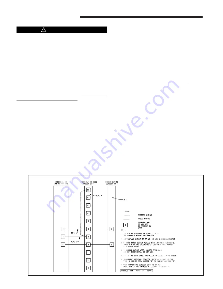
41A -Communicating Indoor Unit with Communicating Comfort Control and Communicating Outdoor Unit
ELECTRICAL CONNECTIONS
▲
CAUTION
!
Protect from Property Damage
Do NOT connect the furnace line voltage to a GFCI
protected circuit. Failure to follow this warning could
result in property damage.
Make wiring connections to the unit as indicated on the
following field wiring diagram. As with all gas appliances
using electrical power, this furnace shall be connected
into a permanently live electric circuit. It is recommended
that furnace be provided with a separate “circuit
protection device” electric circuit. The furnace must be
electrically grounded in accordance with local codes or
in the absence of local codes with the National Electrical
Code, ANSI/ NFPA 70 or CSA C22.1 Electrical Code, if
an external electrical source is utilized.
The integrated
furnace control is polarity sensitive
.
The hot leg of the 120V power supply must be connected
to the Black power lead as indicated on the wiring
diagram. Provision for hooking up an Electronic Air
Cleaner and/ or Humidifier is provided on the Integrated
Control.
Refer to the Service Facts literature and unit wiring
diagram attached to the furnace.
!
Field Wiring Diagrams
NOTE:
The B/C terminal will require three wires to be con-
nected to the low voltage terminal strip. To make this
easier, create a pigtail using a short length of thermo-
stat wire to connect the three wires to the B/C terminal.
NOTE:
*FD whole house air cleaners with "D" or later in the
14th digit of the model number must use the BAYAC-
CECOMM101 kit when connected for 24 volt mode. *FD
whole house air cleaners with "A", "B", or "C" in the
14th digit of the model number must use the BAYAC-
CECOMM101 kit when connected for 24 volt or commu-
nicating modes. See the BAYACCECOMM101 Installer's
Guide for field wiring.
WHOLE HOUSE AIR CLEANER
CONNECTION


