INSTALLATION INSTRUCTIONS
(CONTINUED)
CONTROL WIRING
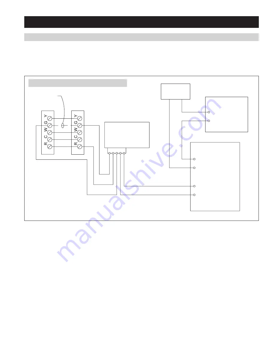
The Steam Humidifier may be connected directly to the humidistat terminals on any Connected Thermostat Controls . If not using a Connected
Control, install manual humidifier control with the Blower Activation Relay . See
Figures 13, 14, 15
for wiring options .
The control circuit operates on 24 VAC . Install manual humidifier control and blower activation relay as shown in
Figure 12
. If protection from
over-humidification is desired, install optional high humidity limit switch at least 4 feet downstream of the dispersion tube .
MANUAL
HUMIDIFIER
CONTROL
TYPICAL 24 VAC
TERMINAL STRIP
IN FURNACE
THERMOSTAT
BLOWER ACTIVATION
RELAY
REMOVE WIRE
“G” TO “G”
HIGH HUMIDITY
LIMIT SWITCH
STEAM
HUMIDIFIER
(OPTIONAL)
NOTES:
1. 18AWG WIRE IS ACCEPTABLE FOR 24V INSTALLATIONS.
2. “FAN PACK” TERMINALS PROVIDE 24 VAC ON CALL FOR HUMIDITY AND REMAIN ENERGIZED FOR
TWO MINUTES AFTER CALL IS SATISFIED.
BLUE (NC)
ORANGE (NO
)
YELLOW (C)
WHITE/YELLOW
WHITE/BLUE
FAN P
ACK
HUMIDIS
TAT
FIGURE 12 – Wiring with Manual Humidifier Control
90-1706
17


