CTV-SVX009D-GB
52
4
UNT-PRC002-GB
Technical Data
FWD
08
12
20
30
45
Power supply
(V/Ph/Hz)
230/1/50
Capacities
Cooling capacity on water (1)
(kW)
5,2
8,3
15
18,8
30,1
Heating capacity on water (2)
(kW)
6,3
11,9
18,9
20,9
38,2
Fan motor
(type)
2 x direct drive centrifugal
Fan power input (3)
(kW)
0,23
0,46
0,65
1,04
1,51
Current amps (3)
(A)
1,1
2,2
3,1
4,7
5,5
Start-up amps
(A)
3,2
5,5
9,3
14,1
16,5
Air flow
minimum
(m
3
/h)
490
980
1400
1800
2700
nominal
(m
3
/h)
820
1650
2300
3000
4500
maximum
(m
3
/h)
980
1970
2600
3600
5400
Main coil
Water entering/leaving connections
(type)
ISO R7 rotating female
(Dia)
3/4"
3/4"
1 1/2"
1 1/2"
1 1/2"
Electric heater (accessory for blower only)
Electric power supply
(V/Ph/Hz)
230/1/50
230/1/50 or 400/3/50
400/3/50
400/3/50
400/3/50
Heating capacity
(kW)
2/4
8
10
12
12
Hot water coil (accessory for blower only)
Heating capacity (4)
(kW)
6,3
12
17,4
22,4
34,5
G2 filter (filter box accessory)
Quantity
2
2
2
2
2
Dimensions ( LxWxth)
(mm)
386x221x8
486x271x8
586x321x8
586*421*8
586*621*8
G4 filter (filter box accessory)
Quantity
-
2
2
2
2
Dimensions ( LxWxth)
(mm)
-
486x264x48
586x314x48
586*414*48
586*614*48
Condensate pump (accessory)
(type)
Centrifugal
Water flow - lift height
(l/h - mm)
24 - 500
Not available for FWD30 and FWD45
Sound level (L/M/H speed)
Sound pressure level (5)
(dB(A))
36/40/43
38/41/44
46/50/53
47/52/57
47/52/58
Sound power level (5)
(dB(A))
46/50/53
48/51/54
56/60/63
57/62/67
57/62/68
Unit dimensions
Width x Depth
(mm)
890 x 600
1090 x 710
1290 x 820
1290 x 970
1290 x 1090
Height
(mm)
250
300
350
450
650
Shipped unit dimensions
Width x Depth
(mm)
933 x 644
1133 x 754
1333 x 864
1333 x 1008
1333*1133
Height
(mm)
260
310
360
460
660
Weight
(kg)
32
46
61
76
118
Colour
galvanised steel
Recommended fuse size
Unit alone (aM/gI)
(A)
8/16
8/16
8/16
8/25
8/25
Unit with electric heater (gI)
(A)
16 (2kW),25 (4kW)
40 (230V),3*16 (400V)
3*20
3*25
3*25
(1) Conditions: Water entering/leaving temperature: 7/12 °C, Air inlet temperature 27/19°C DB/WB - Nominal air flow
(2) Conditions: Water entering/leaving temperature: 50/45 °C, Air inlet temperature 20°C DB - Nominal air flow
(3) At high speed with nominal air flow.
(4) Water entering/leaving temperature 90/70 °C, air inlet temperature 20 °C DB, Nominal air flow.
(5) A rectangular glass wool duct 1m50 long is placed on the blower.The measurement is taken in the room containing the blower unit.
Heat exchanger operating limits:
FWD:
*water temperature: max 100° C
*absolute service pressure: min 1 bar/max 11 bars
Accessories - Hot water coil:
*water temperature: min. +2° C/max. 100° C
*absolute service pressure: min 1 bar/max 11 bars
Cleaning Procedures
It is mandatory to clean regularly the coils for a proper unit
operation. Eliminate pollution and other residual material
help to extend the life of the coils and the unit.
CAUTION! Equipment Damage!
Do not use coil cleaning
agents to clean uncoated GVAF coils. Use clean water only.
Use of coil cleaning agents on uncoated GVAF coils could
cause damage to coils.
Regular coil maintenance, including frequent cleaning-
enhances the unit’s operating efficiency by minimizing
compressor head pressure and amperage draw. The
condenser coil (non-coated and e-coated) should be cleaned
at least once each quarter or more if the unit is located in a
“dirty” or corrosive environment. Cleaning with cleansers or
detergents is strongly discouraged due to the all-aluminum
construction; straight water should prove sufficient. Any
breach in the tubes can result in refrigerant leaks.
Important:
Only in extreme cases should any type of
chemical cleaner or detergent be used on micro channel
coils. If it becomes absolutely necessary because water
alone did not clean the coil, specify a cleaner that is:
• A is pH neutral cleaner.
• An alkaline cleaner that is no higher than 8 on
the pH scale.
• An acidic cleaner that is no lower than 6 on the pH
scale.
• Does not contain any hydrofluoric acids.
Be sure to follow the instructions provided with any cleaner
chosen. Keep in mind that it is still MANDATORY that the
coils are thoroughly rinsed with water after the application
of the cleaner even if the instructions specify a “No Rinse”
cleaner. Cleaners or detergents that are left on the coil due
to improper rinsing will significantly increase the possibility
of corrosion damage on the micro channel coil.
Note:
Quarterly cleaning (or more for harsh environment)
is essential to extend the life of a MCHE coil and is required
to maintain warranty coverage. Failure to clean a MCHE coil
will void the warranty and may result in reduced efficiency
and durability in the environment.
WARNING! Hazardous Voltage!
Disconnect all electric
power, including remote disconnects before servicing.
Follow proper lockout/ tagout procedures to ensure the
power cannot be inadvertently energized. Failure to
disconnect power before servicing could result in death or
serious injury.
1. Disconnect Power to the unit.
2. Wear proper personal protection equipment such as a
face shield, gloves and waterproof clothing.
3. Remove enough panels from the unit to gain safe
access to the micro channel coil.
Note:
It is better to clean the coil from the opposite direction
of normal air flow (inside of unit out) because this allows
the debris to be pushed out rather than forced further into
the coil.
1. Use a soft brush or vacuum to remove base debris or
surface loaded fibers from both sides of the coil.
Note:
Remove solid residue is essential to preserve
performance of the coil and avoid corrosion over the length
of the product life.
2. Using a sprayer and water ONLY, clean the coil
following the guidelines below.
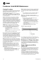
a. Sprayer nozzle pressure should not exceed 40 bars.
b. The maximum source angle should not exceed
25 degrees (Figure 22) to the face of the coil. For
best results spray the micro channel perpendicular
to face of the coil.
c. Spray nozzle should be approximately 5 to 10 cm
from the coil surface.
d. Use at least a 15º fan type of spray nozzle.
Figure 23 – Sprayer source angle
To avoid damage from the spray wand contacting the coil,
make sure the 90º attachment does not come in contact with
the tube and fin as abrasion to the coil could result.
Maintenance of Flanges Connection
It is mandatory to apply marine grease all around the coil
flange connections to the piping on a regular basis (for
instance twice a year) to avoid traps of moisture and dirt in
the gasket recess.
Repair / Replacement of Micro
channel Coil
Micro channel coils are considerably more robust in design
than tube and fin condenser coils, however they are not
indestructible. When damage or a leak occurs in the field, it
is possible to temporarily repair the coil until another coil
can be ordered.
If the leak is found to be within the tube area of the coil,
a field repair kit (KIT16112) is available through your local
Trane parts center. Because of the all-aluminum construction
and aluminum’s high thermal expansion rate, a leak located
at or on the header assembly cannot be repaired.
Condenser Coils MCHE Maintenance


