Alarms and Troubleshooting
56
OAU-SVX005C-EN
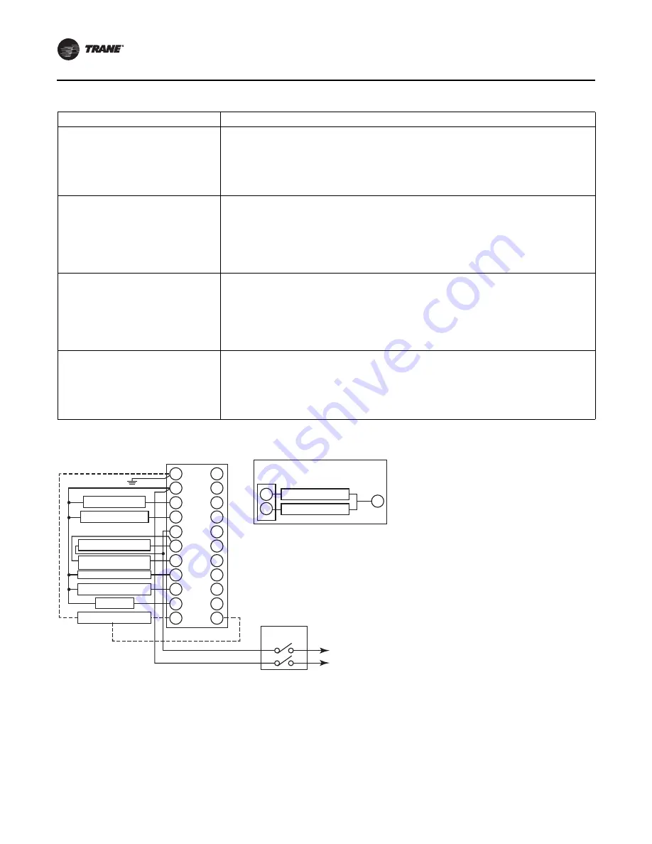
1. RM7895, RM7896; 120 Vac, 50/60 Hz; EC7895; 220–
240 Vac, 50/60 Hz Power Supply. Provide disconnect
means and overload protection as required.
2. Do not connect any wires to unused terminals.
3. For EC7895, A 220 to 240 Vac to 120 Vac, 10 VA
minimum stepdown transformer (not provided) must
be used to drive the shutter.
4. See flame detector specifications for correct wiring.
5. For RM7896A1048 (only), Ignition Terminal 1 is de-
energized when flame is proven.
6. Airflow switch check feature is for the RM7895,
RM7896B.
7. RM7896A,B (only).
Prepurge Period
• Airflow lockout feature is enabled and the airflow switch opens
• Ignition/pilot valve terminal is not energized
• No flame present at end of PFEP
• Main valve terminal is energized
• Delayed main valve terminal is energized (RM7895C/D)
• Internal system fault occurred
• Purge card is removed
• Purge card is bad
Pilot Flame Establishing Period (PFEP)
• Airflow lockout feature is enabled and the airflow switch does not close after 10 seconds or within the
specified purge card timing
• Flame signal is detected after 30 seconds
• Ignition/pilot valve/intermittent pilot valve terminal is energized
• Main valve terminal is energized.
• Delayed (2
nd
stage) main valve terminal is energized (RM7895C/D, EC7895C, RM7896C/D)
• Internal system fault occurred
• Purge card is removed
• Purge card is bad
Main Flame Establishing Period (MFEP)
-RM7895C/D, EC7895C, RM7896C/D
• Airflow lockout feature is enabled and the airflow switch opens
• Ignition terminal is energized
• Ignition/pilot valve terminal is not energized
• Main valve terminal is not energized
• Delayed main valve terminal is energized
• No flame present at end of MFEP
• Internal system fault occurred
• Purge card is removed
• Purge card is bad
Run Period
• No flame present
• Airflow lockout feature is enabled and the airflow switch opens
• Interrupted pilot valve terminal is energized (RM7895C/D,EC7895C, RM7896C/D)
• Main valve terminal is not energized
• Delayed (2
nd
stage) main valve terminal is not energized (RM7895C/D,EC7895C, RM7896C/D)
• Internal system fault occurred
• Purge card is removed
• Purge card is bad
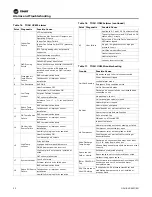
Table 20. Troubleshooting guide for flame relays during problem of safety shutdown (lockout) (continued)
Occurs In
Occurs If
Figure 23.
Wiring subbase and sequence chart for RM7895A/B, EC7895A, RM7896A/B
G
L2
3
4
5
6
7
8
9
10
F
10
8
L2
12
13
14
15
16
17
18
19
20
21
22
Q7800
Line Voltage Alarm
Blower Motor (Blower)
Intermittent Pilot Ignition
Main Fuel Valve(s)
Ignition
Flame Detector
Master
Switch
L1 (Hot)
L2
(See Note 1)
Burner Controller/Limits
Lockout Interlock
Including Airflow Sw.
(See Note 4)
(See Note 3)
(See Note 2)
Ignition Transformer
Main Valve
For Direct Spark Ignition
(Oil or Gas)
L1


