Installation
RT-SVX35H-EN
61
Table 16. GBAS voltage vs. setpoint
Unit Type
Setpoint
Input Voltage
(a)
Setpoint Range
VAV
CV
X
X
Unoccupied Zone Cooling Setpoint
0.5 to 4.5 vdc
50°F to 90°F
X
Occupied Zone Cooling Setpoint
0.5 to 4.5 vdc
50°F to 90°F
X
X
Occupied Zone Heating Setpoint
0.5 to 4.5 vdc
50°F to 90°F
X
S/A Cooling Setpoint
0.5 to 4.5 vdc
40° to 90°F
X
S/A Heating Setpoint (VAV Hydro Only)
0.5 to 4.5 vdc
40° to 180°F
X
X
Space Static Pressure Setpoint
0.5 to 4.5 vdc
0.03 to 0.3 IWC
X
Supply Duct Static Pressure Setpoint
0.5 to 4.5 vdc
0.00 to 5.0 IWC
Notes:
1.
Voltage inputs less than 0.5 will be interpreted as 0.5 vdc.
2.
Voltage inputs higher than 4.5 will be interpreted as 4.5 vdc.
(a) The actual inputted value will be displayed on the Human Interface.
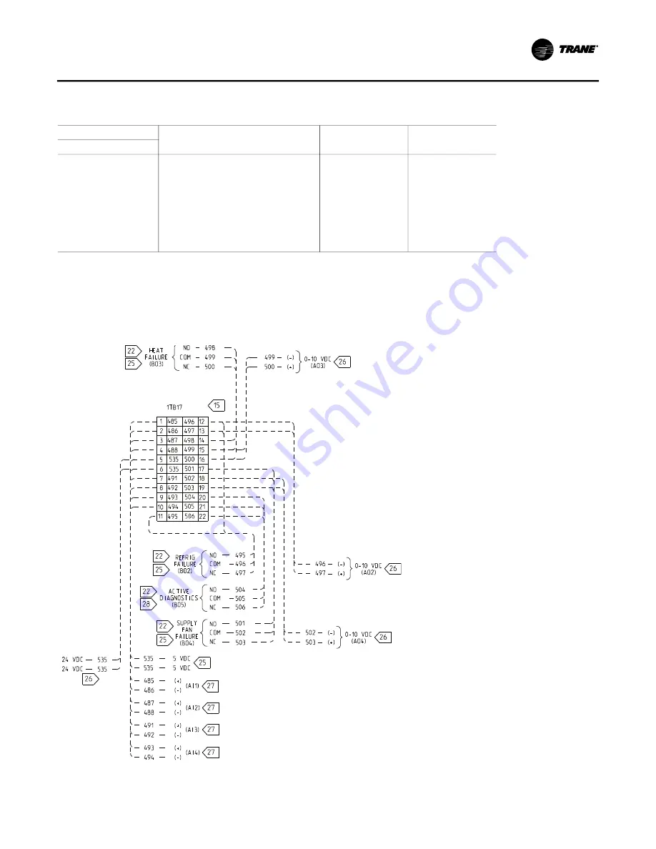
Figure 36. Typical GBAS analog input wiring schematic for W_HE casings 2-9 CV or VAV control options.
Summary of Contents for IntelliPak WEHE Series
Page 15: ...General Information RT SVX35H EN 15 Figure 1 Unit component layout and ship with locations...
Page 17: ...Installation RT SVX35H EN 17 Figure 2 Typical control module location...
Page 44: ...Installation 44 RT SVX35H EN Figure 27 Typical field power wiring for W_HE casings 2 through 6...
Page 56: ...Installation 56 RT SVX35H EN Figure 32 Wiring notes for CV controls...
Page 60: ...Installation 60 RT SVX35H EN Figure 35 Wiring notes VAV...
Page 68: ...System Start up 68 RT SVX35H EN Figure 38 Typical fenwall ignition control system...
Page 69: ...System Start up RT SVX35H EN 69 Figure 39 Typical Fenwall ignition control system...


