General Information
CLCH-SVX08C-EN
7
Description
The gas heat section consists of a drum-and-tube heat
exchanger, burner, gas train components, and a control
panel for electrical connections. It is an integral part of the
entire air-handling system.
An access door is provided for service and maintenance of
the burner and gas train components.
The gas heat section must be in a blow-thru position
downstream from the supply fan. Downstream sections
must be separated by a blank access section and discharge
temperatures must be controlled so as not to exceed the
temperature limits of components in the downstream
sections.
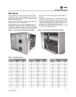
Depending on the heater size, an external vestibule that
extends the width of the gas heat section may be used to
house the burner and gas train components (see
The external vestibule, if required, ships attached to the
gas heat section. Some heaters have gas train
components in an internal vestibule (see
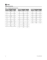
for vestibule locations.
Figure 2. Gas heat section with external vestibule
Figure 3. Gas heat section with internal vestibule
Table 2.
Vestibule locations
Unit Size
Gas Output
(MBh)
Vestibule
Type
Unit Size
Gas Output
(MBh)
Vestibule
Type
Unit Size
Gas Output
(MBh)
Vestibule
Type
6
200
Ext
35
320/360
Int
66
700
Int
6
300
Ext
35
560
Int
66
860
Int
8
200
Ext
35
700
Int
66
1000
Int
8
300
Ext
35
860
Int
66
1250
Int
10
200
Ext
35
1000
Ext
66
1500
Int
10
320/360
Ext
35
1250
Ext
66
1750
Int
12
200
Int
35
1500
Ext
66
2000
Ext
12
320/360
Ext
35
1750
Ext
66
2400
Ext
14
200
Int
40
560
Int
80
860
Int
14
320/360
Ext
40
700
Int
80
1000
Int
17
200
Int
40
860
Int
80
1250
Int
17
320/360
Ext
40
1000
Ext
80
1500
Int
17
560
Ext
40
1250
Ext
80
1750
Int
17
700
Ext
40
1500
Ext
80
2000
Ext
21
200
Int
40
1750
Ext
80
2400
Ext


