background image

Installation

10

 HDWA-SVN002D-EN

76

76

77

77

78

78

79

79

80

80

81

81

82

82

83

83

84

84

85

85

86

86

87

87

88

88

89

89

90

90

91

91

92

92

93

93

94

94

95

95

96

96

97

97

98

98

99

99

100

100

101

101

102

102

103

103

104

104

105

105

106

106

107

107

108

108

109

109

110

110

111

111

112

112

113

113

114

114

2F1

15A

2F2

15A

201A

202A

INSET A

INSET A

SEE

INSET A

400VAC

H1-H3

380VAC

H1-H2

415VAC

H1-H4

1D

TO 2Q1-2

LINE 4 OR 33

TO 2X8-1

LINE 84

TO 2F8

LINE 88

211A

203A

2D

TO 2Q1-4

LINE 5 OR 34

260AF

2X8-1

211A

GND

GND

GND

GND

GND

GND

260AM

260AN

260AP

DOOR GROUNDS

2K1

14

13

2X3-9

2XJ1-3

2XJ1-4

2XJ5-1

2XJ5-2

2XP1-3

2XP1-4

2XP5-1

2XP5-2

2X3-10

4B3

2X3-11

4B2

P

228B

228A

229A

229B

229C

BLK

BLK

2X6-1

211Y

2X3-12

215B

215B

RELAY 1

RELAY 2

SAFE STOP

OPTION D

MODBUS

2T1

DRIVE MODULE CONTROL CARD

FC-X02

01

02

03

04

05

06

13

33

37

(-) 35

(+) 36

D-OUT 29

D-COM 20

D-IN 19

24VDC 12

69

68

61

SERIAL

PORT

USB

FK100

213A

2X5-1

212B

212A

211B

215A

2F13

11

12

240A

244A

1P1

MK100

TO 2K3-MK110

LINE 60

2F7

5A

2F8

20A

203A

203A

203B

,B

2X5-2

204G

,G

204B

204B

4M7

12

G

2M1

12

G

2M2

12

G

2XJ4-1

2XJ4-2

2XJ4-3

2XP4-1

2XP4-2

2XP4-3

2K1

95

2K1

10

6

2X2-2

2X2-3

GND

GND

COOLING PUMP MOTOR

2X6-2

2K1-104,106

204D

,D

204C

204C

205B

205A

211D

260J

211C

211C

260K

206B

,B

206A

206A

211E

,E

211X

,X

260E

260E

260F

,F

2X6-3

DRIVE

ENCLOSURE FANS

OPTIONAL

SINGLE DRIVE

1X2

227A

1D

2D

RED

TO 2T1A-8

LINE 48

WHT

TO 2T1A-7

LINE 47

BLK

TO 2T1A-6

LINE 46

RED

TO 2T1A-11

LINE 45

WHT

TO 2T1A-10

LINE 44

BLK

TO 2T1A-9

LINE 43

SEE

INSET B

INSET B

INSET B

OPTIONAL TWIN DRIVE

204B

TO 2X5-2

LINE 104

204B

TO 2X9-01

LINE 77

OPTIONAL

TWIN DRIVE

212B

TO 2X5-1

LINE 86

212B

TO 2X9-02

LINE 78

OPTIONAL

TWIN DRIVE

2X9

06

05

04

03

02

01

WHT

TO 1K20 IMC-B

LINE 172

BLK

WF3

GRNGRN

WF12

TO 2XJ2

LINE 264

BLK

WHT

2X8-2

GND

,C

2T4

120VAC 60HZ

460VAC

H1

H2

H4

X4

X1

H3

X3

X2

2T4

110VAC 50HZ

X1

X2

X4

H4

H1

X3

H2

H3

216A

TO 2T7-V(-)

LINE 139

217A

TO 2T7-V(+)

LINE 139

Summary of Contents for KIT19017

Page 1: ...g up and servicing of heating ventilating and air conditioning equipment can be hazardous and requires specific knowledge and training Improperly installed adjusted or altered equipment by an unqualif...

Page 2: ...hazardous situation which if not avoided could result in minor or moderate injury It could also be used to alert against unsafe practices NOTICE Indicates a situation that could result in equipment o...

Page 3: ...e the trademarks of their respective owners Revision History General Information updates Part number for Schematic Updated Installation chapter WARNING Follow EHS Policies Failure to follow instructio...

Page 4: ...4 HDWA SVN002D EN Table of Contents General Information 5 Parts List for KIT19017 5 Installation 6 Check Upgrade the UC800 Firmware Version 12 Battery Charge 13 Check UPS Power Status 13...

Page 5: ...e operation Table 1 Parts list for KIT19017 Mnemonic Part Description Quantity CNT08155 UPS N1C L2000 IR 1 BRK05234 Bracket UPS Retrofit Mounting 1 WIR10207 Harness 120V UPS Power 1 WIR10514 Harness U...

Page 6: ...ervicing Refer to the manufacturer s recommendations for proper discharge time as DC bus capacitors retain hazardous voltages after input power has been disconnected Follow proper lockout tagout proce...

Page 7: ...nstallation HDWA SVN002D EN 7 7 Install the mounting bracket to back of the new UPS using the M8 x 16 screws provided See following figure Figure 4 Mounting bracket installed Figure 5 Mounting bracket...

Page 8: ...lation 8 HDWA SVN002D EN 8 Install the UPS in the center section of the panel as shown in the following figure 9 UsewireharnessesWIR10207andWIR10514provided Figure 6 UPS installation Figure 7 Wire har...

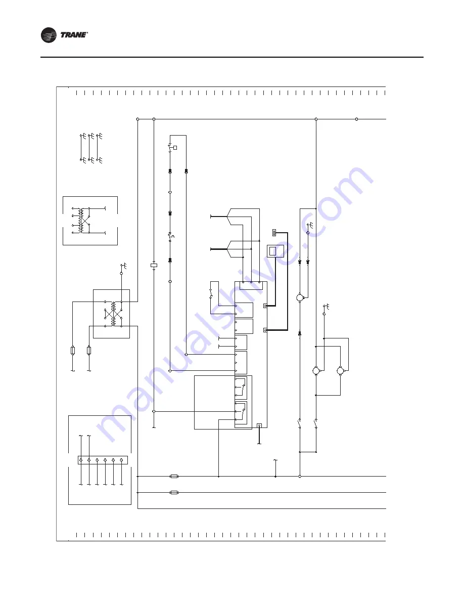
Page 9: ...Installation HDWA SVN002D EN 9 10 Connect power and control wiring as shown in the schematic Figure 8 Power and control wiring connection...

Page 10: ...19 24VDC 12 69 68 61 SERIAL PORT USB FK100 213A 2X5 1 212B 212A 211B 215A 2F13 11 12 240A 244A 1P1 MK100 TO 2K3 MK110 LINE 60 2F7 5A 2F8 20A 203A 203A 203B B 2X5 2 204G G 204B 204B 4M7 1 2 G 2M1 1 2...

Page 11: ...LINE 273 271A TO 2XJ3 2 LINE 272 2XP11 H N G 2X1 6 GND 2XP10 H N G 2X1 3 GND 2X3 2 2X3 1 1XP3 1 1XJ3 1 1XP3 2 1XJ3 2 2X1 5 2X1 4 2T10 50VDC H N G 2T9 50VDC H N G 2T8 50VDC H N G 2F3 10A 150VDC TO MBC...

Page 12: ...firmware or later skip this step Important Firmware 2 01 or new is required Check Upgrade the UC800 Firmware Version To check and or upgrade the firmware on the UC800 see the instructions below 1 Conn...

Page 13: ...UPS turns on refer to the following figure The UPS is in the battery mode and will buzz alarm every few seconds during battery test b Press and hold the ON button again for 3 seconds to check the buzz...

Page 14: ......

Page 15: ......

Page 16: ...re committed to using environmentally conscious print practices Trane by Trane Technologies NYSE TT a global climate innovator creates comfortable energy efficient indoor environments for commercial a...

Reviews: