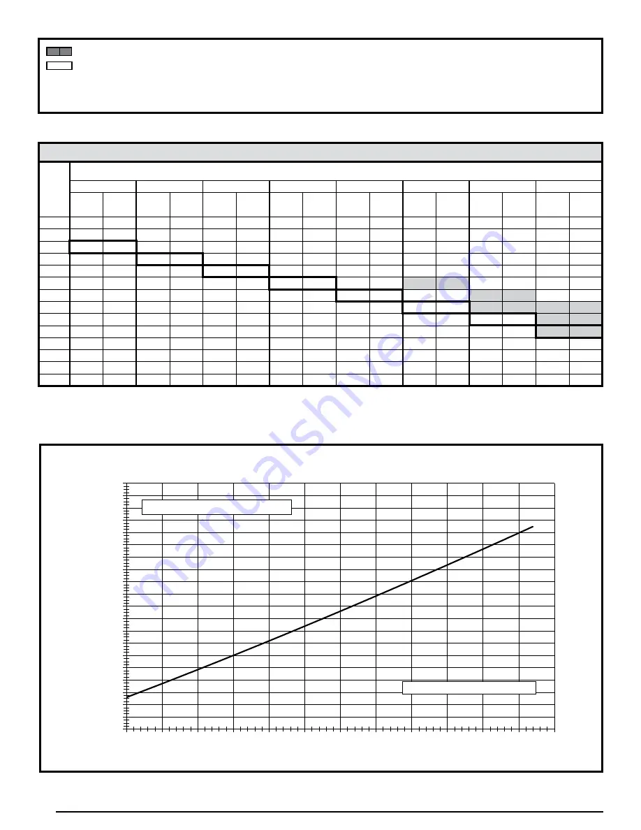
background image

28

200

220

240

260

280

300

320

340

360

380

400

420

440

460

480

500

520

540

560

580

600

75

80

85

90

95

100

105

110

115

120

125

130

135

Liquid Pressure (psig)

Liquid Temperature (F)

5 Ton  Charging Chart - Cooling

Add refrigerant when below curve

Remove refrigerant when above curve

Figure 13. Charging Chart for 5 Ton Models

048K SERIES

SUCT.

PRESS.

OUTDOOR TEMPERATURE (°F)

70

75

80

85

90

95

100

105

LIQ.

PRESS.

DIS.

TEMP.

LIQ.

PRESS.

DIS.

TEMP.

LIQ.

PRESS.

DIS.

TEMP.

LIQ.

PRESS.

DIS.

TEMP.

LIQ.

PRESS.

DIS.

TEMP.

LIQ.

PRESS.

DIS.

TEMP.

LIQ.

PRESS.

DIS.

TEMP.

LIQ.

PRESS.

DIS.

TEMP.

127

248

130

129

250

135

273

134

131

252

140

275

139

298

139

133

257

141

277

144

300

144

323

144

135

260

143

282

146

303

148

326

148

349

148

137

285

149

307

151

328

153

351

153

374

153

139

310

155

332

156

353

157

376

157

399

158

141

335

160

356

161

378

162

401

162

424

163

143

338

163

360

165

381

166

403

166

426

167

145

363

169

385

170

406

170

428

170

147

388

174

410

174

431

175

149

413

179

435

179

151

438

184

153

Table 14. Charging Table for 4 Ton Models


Shaded boxes indicate flooded conditions.


Rated design values. The suction pressure will be lower than design value if indoor air flow, entering dry bulb, or 

entering wet bulb temperatures are lower than design.

1. All pressures are listed in psig and all temperatures in ° F

2. Discharge temperatures greater than charted values indicate an undercharged system.

Summary of Contents for NO Series

Page 1: ...st be performed by a qualified installer service agency or the gas supplier Nepasentreposerniutiliserdel essencenid autresvapeurs ou liquides inflammables dans le voisinage de cet appareil ni de tout autre appareil QUE FAIRE SI UNE ODEUR DE GAZ EST DÉTECTÉE Ne mettre en marche aucun appareil Ne toucher aucun interrupteur électrique ne pas utiliser de téléphone dans le bâtiment Quitter le bâtiment ...

Page 2: ...ing Adjusting Firing Rate 15 Manifold Pressure Adjustment 15 Verifying Over Temperature Limit Control Operation 15 Verifying Burner Operation 15 Verify Operation of the Supply Air Limit Switch 15 OPERATING SEQUENCE 16 Heating Cycle 16 Cooling Cycle 16 Fan Mode 16 EQUIPMENT MAINTENANCE 16 TROUBLESHOOTING 18 FIGURES TABLES 19 Figure 10 Unit Dimensions 19 Table 4 Center of Gravity Unit Shipping Weigh...

Page 3: ...llychargedwithR 410Arefrigerant andreadyforinstallation Whenasystemisinstalled according to these instructions no refrigerant charging is required If repairs make it necessary for evacuationandcharging itshouldonlybeattempted by qualified trained personnel thoroughly familiar with this equipment Some local codes require licensed installation service personnel to service this type of equipment Unde...

Page 4: ... 1 page 5 This unit is designed only for outdoorinstallationsandshouldbelocatedwithconsideration of minimizing the length of the supply and return ducts Consideration should also be given to the accessibility of fuel electric power service access noise and shade AirDuctsmustbeinstalledinaccordancewiththestandards of the National Fire Protection Association Standards for Installation of Air Conditi...

Page 5: ...e installing the unit Locating the Equipment Clearance in accordance with local installation codes the requirements of the gas supplier and the manufacturer s installation instructions Dégaugement conforme aux codes d installation locaux aux exigences du fournisseur de gaz et aux instructions d installation du fabricant A clearance of at least 36 inches from the blower access panel and from the lo...

Page 6: ... suivies pour chacun des appareils raccordés au système de ventilationaumomentdesamiseenmarche celapeut entraîner une intoxication au monoxyde de carbone ou la mort Les étapes suivantes doivent être suivies pour chacun des appareils raccordés au système de ventilation au moment de sa mise en marche alors que tous les autres appareils raccordés au système de ventilation ne sont pas en marche 1 Scel...

Page 7: ...g shall be used This unit must be vented to the outdoors WARNING This unit is intended for outdoor installation only Do not vent the unit through a conventional venting system A vent cover assembly has been supplied with the unit and can be found secured to the gas controls within the control areaofthisunit Theventcoverassemblymustbeinstalled to assure proper operation of the unit Figure 2 Vent As...

Page 8: ...g capacity Duct work should be attached directly to the unit flanges for horizontal applications If roof curb is installed the ducts must be attached to the curb duct supports not the unit It is recommended that the outlet duct be provided with a removableaccesspanel Theopeningshouldbeaccessible when the unit is installed in service and shall be sizes so that smoke or reflected light may be observ...

Page 9: ... to seal 6 Remove and discard the two wood supports beneath the unit Condensate Drain Condensate is removed from the unit through the 3 4 female pipe fitting located on the front side of the unit See Figure 5 page 10 A suitable air filter must be installed upstream of the evaporator coil of the return air system Refer to Table 1 for recommended external filter sizes All return air must pass throug...

Page 10: ...tein Au moment de l entretien des commandes étiquetez tous les fils avant de les débrancher S assurer de les raccorder correctement S assurerquel appareilfonctionneadéquatement aprés l entretien Electrical connections must be in compliance with all applicable local codes and ordinances and with the current revision of the National Electric Code ANSI NFPA 70 For Canadian installations the electrica...

Page 11: ...g diagram before making any electrical connections to the outdoor unit See Figure 12 Units are shipped from the factory wired for 230 volt transformer operation Connect the line voltage leads to the terminals on the contactor inside the control compartment Thermostat Low Voltage Connections This unit is designed to operate from a 24 VAC Class II control circuit A single stage cooling single stage ...

Page 12: ...lt in serious injury death or property damage Installation and service must be performed by a qualified installer service agency or the gas supplier Do not store or use gasoline or other flammable vapors and liquids in the vicinity of this or any other appliance WHAT TO DO IF YOU SMELL GAS Do not try to light any appliance Do not touch any electrical switch do not use any phone in your building Le...

Page 13: ...s Ne jamais vérifier la présence de fuites de gaz au moyen d une flamme nue Vérifier tous les raccords en utilisant une solution savonneuse commerciale conçue spécialement pour la détection de fuites Un incendie ou une explosion risque de se produire ce qui peut entraîner la mort des blessures ou des dommages matériels After the gas piping to the unit is complete all connections must be tested for...

Page 14: ...is wired correctly The thermostat function switch should be set to OFF and the thermostat fan switch should be set to AUTO Start Up Procedure WARNING If this unit is equipped with crankcase heaters allow 24 hrs for heating of the refrigerant compressor crankcase prior to start up or anytime the power has been removed for more than 12 hrs Failure to comply may result in damage or cause premature fa...

Page 15: ...ighten the regulator capscrew over the adjustment screw Verifying Over Temperature Limit Control Operation 1 Verify the louvered control access panel is in place and that there is power to the unit 2 Block the return airflow to the unit by installing a close off plate in place of or upstream of the filter 3 Set the thermostat above room temperature and verify the units operating sequence on page 1...

Page 16: ...densingsectionisde energized and the control continues to run the fan for a period of 60 seconds Fan Mode WhenthethermostatenergizestheGterminalforcontinuous fan without calling for heat or cooling the indoor fan is energized on the selected FAN speed See Figure Page The control defaults to MEDIUM HIGH if the movable jumper is not attached If a call for cooling occurs during continuous fan the blo...

Page 17: ...tion The bearings in the blower motor and inducer blowerusedinthesefurnacesarepre lubricatedandsealedby the manufacturer No further oiling of the bearings is required for the life of the motor Cleaning of Flame Sensor If the flame sensor is suspect for Loss of Flame fault code the sensor can be cleaned to see if that remedies the issue Follow steps 1 10 See Figure 14 page 29 for component location...

Page 18: ... 5 failed attempts for ignition and will try again every hour if the call for heat remains Iftheinducerblowerisoperatinganditemsabovehavebeen verified check the limit switch circuit and reset if necessary See Figure 14 page 29 for component location If the furnace operates when the limit switch circuit is reset contact a qualified service technician to identify and repair the problem If the furnac...

Page 19: ...ng Horizontal Return Duct Opening 4 0 1 75 9 75 24 75 16 0 Condensing Coil 13 5 16 0 16 0 C 13 5 Figure 10 Unit Dimensions MODEL NUMBER UNIT WEIGHT SHIPPING WEIGHT CENTER OF GRAVITY HEIGHT IN INCHES C A B WITH BASE RAILS WITHOUT BASE RAILS 4YCL4024A1055A 390 406 26 5 26 5 35 0 31 3 4YCL4030A1070A 390 406 26 0 26 5 35 0 31 3 4YCL4036A1070A 390 406 26 5 26 5 35 0 31 3 4YCL4042A1100A 438 455 27 26 5 ...

Page 20: ...64 1131 66 1083 69 1030 73 Tap T3 1513 50 1461 51 1402 53 1355 55 1297 58 1243 60 1202 62 1147 65 Tap T4 Tap T5 4YCL4048A1100A 35 65 Tap T1 999 75 928 81 868 86 806 93 741 101 696 108 629 119 564 133 Tap T2 1390 54 1337 56 1299 58 1235 61 1173 64 1131 66 1083 69 1030 73 Tap T3 1513 50 1461 51 1402 53 1355 55 1297 58 1243 60 1120 67 1147 65 Tap T4 Tap T5 4YCL4060A1100A 35 65 Tap T1 1589 47 1498 50 ...

Page 21: ...323 1278 1228 1166 1100 Tap T4 1555 1505 1448 1400 1351 1297 1238 1178 Tap T5 1920 1872 1836 1785 1728 1699 1645 1592 4YCL4042A1100A Tap T1 1098 1020 954 886 814 765 691 620 Tap T2 1527 1469 1418 1357 1289 1243 1190 1132 Tap T3 1663 1605 1541 1489 1425 1366 1321 1260 Tap T4 1950 1884 1842 1790 1743 1687 1637 1571 Tap T5 2031 1992 1921 1871 1820 1770 1711 1650 4YCL4048A1100A Tap T1 1098 1020 954 88...

Page 22: ...NE REVOLUTION SECONDS CUBIC FEET PER REVOLUTION OF GAS METER 1 5 10 10 360 1 800 3 600 12 300 1 500 3 000 14 257 1 286 2 571 16 225 1 125 2 250 18 200 1 000 2 000 20 180 900 1 800 22 164 818 1 636 24 150 750 1 500 26 138 692 1 385 28 129 643 1 286 30 120 600 1 200 32 113 563 1 125 34 106 529 1 059 36 100 500 1 000 38 95 474 947 40 90 450 900 42 86 429 857 44 82 409 818 46 78 391 783 48 75 375 750 ...

Page 23: ... compagnie du gaz en utili sant le téléphone d un voisin A défaut de la compagnie du gaz avertir le service des pompiers C Enfoncer ou faire tourner le robinet à gaz à la main seulement Ne jamais utiliser d outils S il n est pas possible de faire tourner ou d enfoncer le robinet à la main ne pas essayer de le réparer Faire appel à un spécialiste Forcer ou tenter de réparer le robinet pourrait être...

Page 24: ...nuous Flash On Alternating Flash R COMPRESSOR C R S OUTDOOR FAN MOTOR C F H C S Y2 A1 Y C W1 G R IGNITOR FLAME SENSOR BLOWER MOTOR SUPPLY AIR LIMIT PRESSURE SWITCH 1 2 1 2 T5 T1 N G L C T4 T3 T2 1 1 2 2 3 3 4 4 INDUCER TEMP LIMIT 1 2 3 4 5 6 1 2 3 4 5 6 7 8 9 R C Y G W LOW ML MH HIGH EAC L1 XFMR HUM COM GREEN YELLOW RED 3 AMP FUSE 24V R C TX RX W COM L1A NEUTRALS 24V 24V NOTE FOR BLOWER MOTOR WIRI...

Page 25: ...igerant handling procedures Application Notes Charging Charts Cooling Mode Only This equipments cooling system contains refrigerant under high pressure always use safe practices when servicing the unit Always review the factory literature and safety warnings prior to servicing These units are shipped from the factory with the proper amount and type of refrigerant Always inspect the unit rating lab...

Page 26: ...S DIS TEMP LIQ PRESS DIS TEMP LIQ PRESS DIS TEMP LIQ PRESS DIS TEMP LIQ PRESS DIS TEMP LIQ PRESS DIS TEMP LIQ PRESS DIS TEMP 136 244 136 138 246 141 268 137 140 248 146 270 142 292 138 142 254 144 272 147 294 143 316 140 144 258 146 278 147 296 148 319 145 341 142 146 281 150 302 150 321 149 343 146 365 144 148 305 153 325 152 345 151 367 148 390 146 150 329 156 349 154 369 152 392 150 414 148 152...

Page 27: ...PRESS DIS TEMP LIQ PRESS DIS TEMP LIQ PRESS DIS TEMP LIQ PRESS DIS TEMP LIQ PRESS DIS TEMP LIQ PRESS DIS TEMP LIQ PRESS DIS TEMP LIQ PRESS DIS TEMP 125 252 116 127 254 121 276 121 129 256 126 278 126 300 127 131 261 126 280 131 302 132 324 133 133 265 129 285 133 304 137 326 137 348 139 135 288 136 309 139 328 142 350 143 373 145 137 312 142 332 145 353 147 375 149 397 151 139 336 149 356 151 377 ...

Page 28: ...1 252 140 275 139 298 139 133 257 141 277 144 300 144 323 144 135 260 143 282 146 303 148 326 148 349 148 137 285 149 307 151 328 153 351 153 374 153 139 310 155 332 156 353 157 376 157 399 158 141 335 160 356 161 378 162 401 162 424 163 143 338 163 360 165 381 166 403 166 426 167 145 363 169 385 170 406 170 428 170 147 388 174 410 174 431 175 149 413 179 435 179 151 438 184 153 Table 14 Charging ...

Page 29: ... prevents furnace operation with excessive flue blockage or improper inducer operation Main Air Limit Switch Prevents the air temperature leaving the furnace from exceeding the maximum allowable outlet air temperature Temperature Limit Switch Verifies the inducer is drawing combustion gases through the heat exchanger properly The temperature switch prevents furnace operation in the event of flue o...

Page 30: ...30 ...

Page 31: ...31 ...

Page 32: ... This includes being able to install the product according to strict safety guidelines and instructing the customer on how to operate and maintain the equipment for the life of the product Safety should always be the deciding factor when installingthisproductandusingcommonsenseplaysanimportantroleaswell Pay attention to all safety warnings and any other special notes highlighted in the manual Impr...

Reviews: