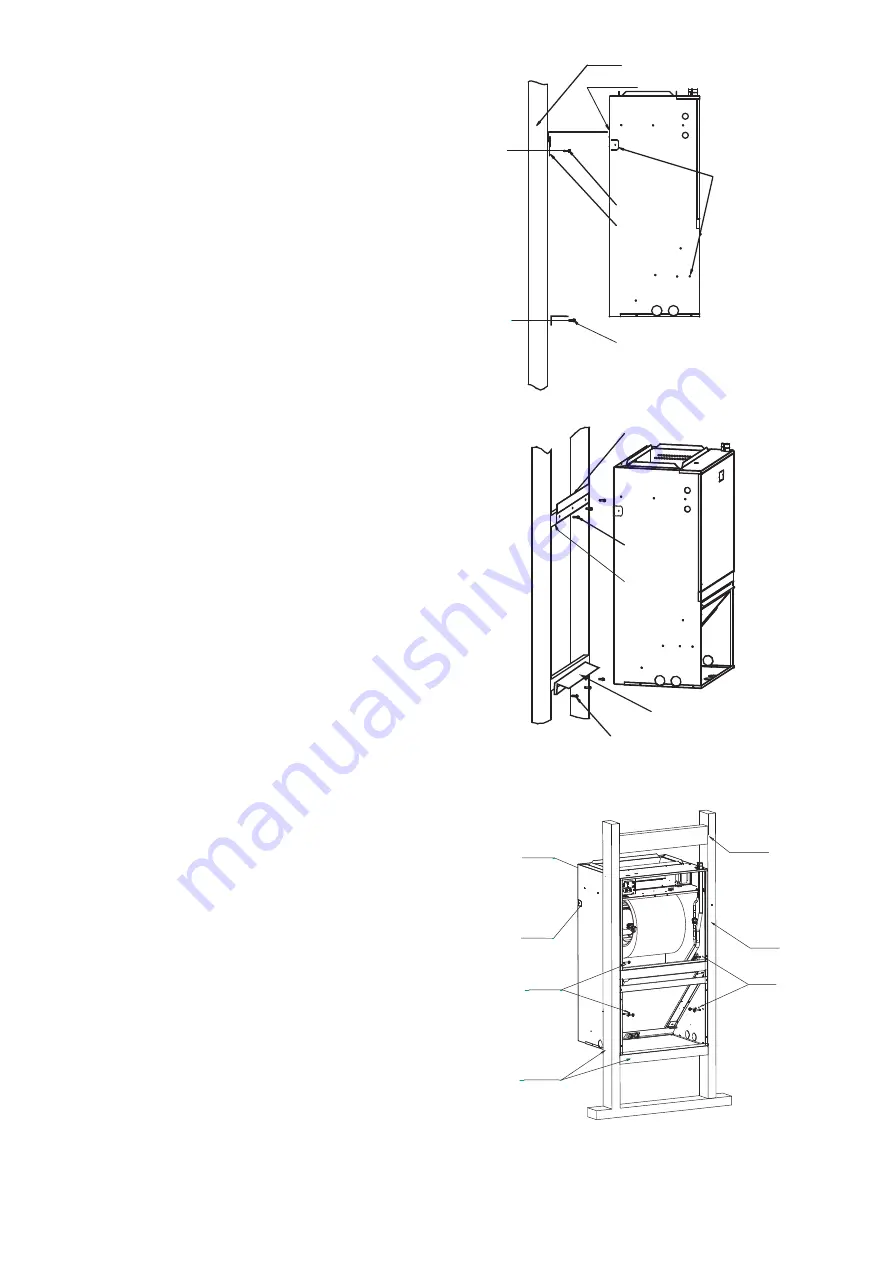
Carefully unpack the unit and inspect the contents for damage. If
any damage is found at the time of delivery, proper notification and
claims should be made with the carrier.
Check the rating plate to assure model number and voltage.
Furthermore, check that kits match with what was ordered. The
manufacturer should be notified within 5 days of any discrepancy or
parts shortage.
The small air handler should be centrally located and may be
installed in a closet, alcove, utility room, or basement. Minimum
clearances must be met.
The air handler comes standard with two different options for
mounting, wall mount or frame mount. Both mounting options require
the unit to be level from side to side and from front to back in order to
allow condensate to properly drain from the unit. Failure to do this will
result in condensate leaking out from the unit, potentially causing
structural damage to the surrounding support structures, dry wall,
carpet, etc. Also, both mounting structures require the ability to
accommodate a minimum of 150 lb load. Failure to do this will cause
damage to the support structure and potentially damage the unit.
The
air
handler
comes
standard
with
an
upper
and lower wall mount
bracket. Reference Figure 3-1 for more detail.
1.
Remove
lower
wall
mounting
bracket
from
the
back
of
the
unit
by
removing
one
screw
which
attaches
the
bracket
to
the
air
handler.
Note:
Discard the screw after you have removed the wall mounting
bracket.
2.
Install
bracket
on
the
wall
by
using
3
wood
screws
(not
provided).
Make
sure
the
bracket
is
level
in
order
to
provided
proper
drainage
from
the
unit.
Note:
Do
not
attach
the
wall
mounting
bracket
into
unsupported
dry
wall.
Make
sure
that
the
wood
screws
are going into
a structure that can suppport a minimum load of 150 lb.
3.
Lift
the
air
handler
above
the
wall
mounting
bracket and attach the
unit to the installed bracket. Reference Figure 3-1.
4.
Install
the
additional
bottom plate for extra support for this type
mounting (see figure 3-1).
Note:
The
additional
plate
is shipped in the bottom of the shipping
carton (only for 30/36k unit).
3.2.1 WALL MOUNT
Fig. 3-2 FRAME MOUNT
The
air
handler
comes
with
8
clearance
holes
(4
on
each
side).
These
holes
are
used
to
mount
the
air
handler
inside
of
a
frame
structure
(see
Figure
3-2).
When
mounting
in
this
fashion,
make
sure
that
the
wood
screws
are
mounted
from
within
the
air
handler
and
not
outside
of
the
unit.
Install
the
screws
from
outside
the
unit,
and
avoid
damaging
the
coil.
If
the
frame
does
not
provide
support
in
the
front
of
the
unit
and
additional
support
is
needed,
open
up
the
tabs
and
fix
the
unit
to
the
frame
or
other
support
structure
with
screws
(only
for
30K/36K).
Select
a
solid
and
level
site
to
ensure
proper
installation
of
the
frame
mount.
Verify
that
there
is
sufficient space for installation
and maintenance.(See Figure. 3-3)
3.2.2 FRAME MOUNT
Fig. 3-1 WALL MOUNT
Section 3. Installation Instructions
3.1 Unpacking
3.2 Location
WALL STRUTURE
WOOD SCREWS
WOOD SCREWS
PROVIDED WALL
MOUNT BRACKET
NOTE: MOUNTING WALL AND SUPPORTING
STRUCTURE MUST BE ABLE TO SUPPORT A
MINIMUM OF 150 LBS.
PROVIDED AIR HANDLER
MOUNTING BRACKET
NOTE:
IN ORDER TO PREVENT
AIR LEAKAGE,THE TABS
AND SCREW HOLES
NEED TO BE SEALED
UP WHEN THEY ARE
NOT TO BE USED
PROVIDED WALL
MOUNT BRACKET
WOOD SCREWS
SUPPORTING 2
"
X4
"
STRUCTURE
WOOD SCREWS
WALLMOUNT BRACKET
(ONLY FOR 30K/36K)
WALL STRUCTURE
SUPPORTING
2˝X4˝ STRUCTURE
WOOD SCREWS
SUPPORTING
2˝X4˝ STRUCTURE
STUD ATTACHMENT
HOLES
THE TABS
BRACKET PLACEMENT FOR
HANGING IN A CLOSET
damage. See Figure 3-2 for frame mount installation.
studs. If they are not used, the unit may fall down or cause other
on a wood frame, the screws should be used to fix the unit to the
wood screws are recommended. When the unit is installed
˝
#12 x 1 ½
The (8) wood screws are not provided with the unit.
IMPORTANT:
4


