background image

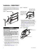
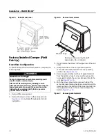
Figure 5.

Reinstall end panel

Installation – FIADMPR103*

10

 ACC-SVN231A-EN

Factory Installed Damper (Field 
Set-Up)

Downflow Configuration

To position damper for downflow operation, complete the 
following steps:

WARNING

Hazardous Voltage!

Failure to disconnect power before servicing could 
result in death or serious injury. 

Disconnect all electric power, including remote 
disconnects before servicing. Follow proper lockout/
tagout procedures to ensure the power can not be 
inadvertently energized. Verify that no power is 
present with a voltmeter.

1. Remove filter access panel.

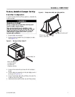
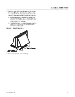
2. Remove the lower screws in the end panel. See 

Figure 6, p. 10

. Lay blockoff angle aside for later 

installation.

Figure 6.

Remove lower screws

3. Do not remove the screws in the upper row of the end 

panel.

4. Grasp the bottom of the end panel and pull the 

economizer assembly outward into the operating 
position. See 

Figure 6, p. 10

.

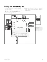
5. Remove approximately 3-inches of gasket material 

from the bottom of each corner post to expose the 
holes used to attach the economizer assembly to the 
unit. See 

Figure 7, p. 10

.

6. With the screws provided, secure each side of the 

economizer assembly by inserting a screw through the 
clearance hole in the bottom of the corner post and into 
the engagement hole in the economizer assembly. 
Refer to 

Figure 7, p. 10

.

Figure 7.

Remove gasket material

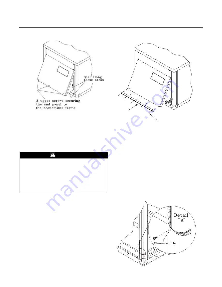
Remove screws and lay blockoff 
angle aside. Do not discard.

Blockoff Angle

Summary of Contents for Precedent FIADMPR102 Series

Page 1: ...0 W D GS 150 300 SAFETY WARNING Only qualified personnel should install and service the equipment The installation starting up and servicing of heating ventilating and air conditioning equipment can b...

Page 2: ...hat is used in these service procedures In addition some states or municipalities may have additional requirements that must also be adhered to for responsible management of refrigerants Know the appl...

Page 3: ...cies those regulations supersede these policies Non Trane personnel should always follow local regulations Introduction ACC SVN231A EN 3 Copyright This document and the information in it are the prope...

Page 4: ...PR102 6 Factory Installed Damper Set Up 7 Downflow Configuration 7 General Information FIADMPR103 8 Inspection 8 Parts List 8 Installation FIADMPR103 9 Field Installed Damper 9 Factory Installed Dampe...

Page 5: ...rted within 15 days 4 If concealed damage is discovered stop unpacking the shipment 5 Do not remove damaged material from the receiving location Take photos of the damage if possible The owner must pr...

Page 6: ...around the channel in the cabinet post Then pivot the damper into the opening in the cabinet Refer to Figure 2 p 6 3 Once the damper is in place lift the damper and panel assembly to align the upper t...

Page 7: ...ntly energized Verify that no power is present with a voltmeter 1 Remove filter access panel 2 Remove bottom blockoff from its shipping location See Figure 4 p 7 Figure 4 Remove bottom blockoff 3 Remo...

Page 8: ...ed damage must be reported within 15 days 4 If concealed damage is discovered stop unpacking the shipment 5 Do not remove damaged material from the receiving location Take photos of the damage if poss...

Page 9: ...r lockout tagout procedures to ensure the power cannot be inadvertently energized Verify with a CAT III or IV voltmeter rated per NFPA 70E that all capacitors have discharged 2 Remove unit end panel r...

Page 10: ...d panel See Figure 6 p 10 Lay blockoff angle aside for later installation Figure 6 Remove lower screws 3 Do not remove the screws in the upper row of the end panel 4 Grasp the bottom of the end panel...

Page 11: ...assembly is in its operating position a Holding the blockoff angle with the holes at the bottom and the bottom angle outward tilt the top forward and insert it into the opening between the economizer...

Page 12: ...g for the required ventilation air use the Symbio service and installation mobile app or Symbio 700 on board UI to adjust the economizer minimum position setpoint BAS in the fresh return air settings...

Page 13: ...bus Common 1 2 3 24 VAC OUT Common IMC IMC 1 2 3 4 IMC Bus White P5 White BK R BL O 24 VAC OUT Common IMC IMC 1 2 3 4 TO UC P4 SHEET 3 1 2 3 4 Common Spare Universal IO 1 Alt 5 VDC OUT Common 5 VDC OU...

Page 14: ...Notes 14 ACC SVN231A EN...

Page 15: ...Notes ACC SVN231A EN 15...

Page 16: ...gn and specifications without notice We are committed to using environmentally conscious print practices Trane and American Standard create comfortable energy efficient indoor environments for commerc...

Reviews:

Related manuals for Precedent FIADMPR102 Series