10
RTAA-IOM-3
Commonly Used
Acronyms
Acronyms used in this manual are
defined below.
OAT
=
Outdoor Air Temperature
BAS
=
Building Automation System
BCL
=
Bidirectional Communications
Link
CAR
=
Circuit Shutdown, Auto Reset
CLS
=
Current Limit Setpoint
CMR
= Circuit Shutdown, Manual
Reset
CWR
= Chilled Water Reset
CWS
= Chilled Water Setpoint
DDT
=
Design Delta-Temperature
Setpoint (i.e., the difference
between entering and leaving
chilled water temperatures)
ENT
=
Entering Chilled Water
Temperature
EXV
=
Electronic Expansion Valve
FLA
=
Full Load Amps
HGBP
= Hot Gas Bypass
HVAC
= Heating, Ventilating and Air
Conditioning
IFW
=
Informational - Warning I/O
Input and Output Wiring
IPC
=
Inter-Processor
Communications
LRA
=
Locked Rotor Amps Leaving
Chilled Water Temperature
MAR
= Machine Shutdown, Auto
Reset
MMR
= Machine Shutdown, Manual
Reset
NEC
=
National Electric Code
PCWS
= Front Panel Chilled Water
Setpoint
PFCC
= Power Factor Correction
Capacitors
PSID
= Pounds-per-Square-inch
Differential (pressure
differential)
PSIG
= Pounds-per-Square-inch
(gauge pressure)
RAS
=
Reset Action Setpoint
RLA
=
Rated Load Amps
RCWS
= Reset Chilled Water Setpoint
(CWR)
RRS
=
Reset Reference Setpoint
(CWR)
SV
=
Slide Valve
Tracer
®
=Type of Trane Building
Automation System
SCI
=
Serial Communications
Interface
UCLS
= Unit Current Limit Setpoint
UCM
= Unit Control Module
(Microprocessor-based)
UCWS
= Unit Chilled Water Setpoint
Unit Description
The 130 thru 400-ton Model RTAA units
are helical-rotary type, air-cooled liquid
chillers designed for installation
outdoors Depending upon rated
capacity, the unit will have two, three or
four compressors. The compressor
circuits are completely assembled,
hermetic packages that are factory-
piped, wired, leak-tested, dehydrated,
and tested for proper control operation
before shipment.
Note:
Packaged units are factory
charged with refrigerant and oil.
Remote evaporator units are shipped
with a holding charge of nitrogen and a
partial charge of oil.
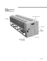
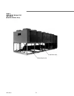
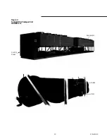
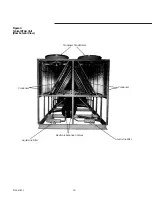
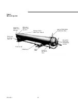
Figures 1 thru 4 show typical RTAA
packaged units and their components.
Figures 5 and 6 show a typical RTAA
Remote Evaporator outdoor unit and
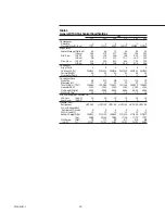
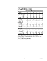
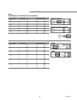
evaporator. Tables 1 and 2 contain
general RTAA mechanical
specifications. Chilled water inlet and
outlet openings are covered for
shipment. Each compressor has a
separate compressor motor starter.
The RTAA series features Trane’s
exclusive Adaptive Control
™
logic,
which monitors the control variables
that govern the operation of the chiller
unit. Adaptive Control logic can correct
these variables, when necessary, to
optimize operational efficiencies, avoid
chiller shutdown, and keep producing
chilled water. An optional remote
display is available to monitor unit
operation from a remote location.
These units feature two independent
refrigerant circuits. Compressor
unloaders are solenoid actuated and oil
pressure operated. Each refrigerant
circuit is provided with filter drier, sight
glass, electronic expansion valve, and
charging valves.
The shell-and-tube type evaporator is
manufactured in accordance with
ASME standards. Each evaporator is
fully insulated and is equipped with
water drain and vent connections.
Packaged units have heat tape
protection to -200 F. Remote
evaporators do not have heat tape.
Summary of Contents for RTAA-130
Page 2: ... American Standard Inc 1991 ...
Page 8: ...8 RTAA IOM 3 ...
Page 24: ...24 RTAA IOM 3 ...
Page 50: ...50 RTAA IOM 3 Figure 30 Refrigerant Circuit Identification ...
Page 52: ...52 RTAA IOM 3 Figure 31 Remote Evaporator Piping Example ...
Page 59: ...59 RTAA IOM 3 Continued from Previous Page See Notes on Next Page ...
Page 63: ...63 RTAA IOM 3 Continued from Previous Page See Notes on Page 61 ...
Page 65: ...65 RTAA IOM 3 Continued from Previous Page See Notes on Page 61 ...
Page 76: ...76 RTAA IOM 3 ...
Page 92: ...92 RTAA IOM 3 Figure 51 Operator Interface Controls ...
Page 120: ...120 RTAA IOM 3 ...
Page 127: ...127 RTAA IOM 3 Continued from Previous Page 2307 1566C ...
Page 128: ...128 RTAA IOM 3 Figure 57 Unit Sequence of Operation RTAA 130 to 200 Tons 2306 9122A ...
Page 132: ...132 RTAA IOM 3 Figure 58 Operator s Log ...
Page 138: ...138 RTAA IOM 3 ...


