100
RTAA-IOM-3
Menu Function
Descriptions and
Selection
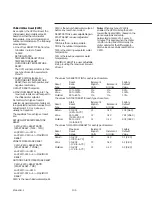
Selecting Variables and Options
All variables and options will be set by
depressing the SET POINT UP and SET
POINT DOWN keys. The setpoints will
be increased or decreased by one least
significant digit (1 F, 0. 1 C, or 1 integer
value) with each key depression. If the
key is held down, the setpoint will
continue to be increased or decreased
until the key is released. The minimum
and maximum values of all setpoints
are limited by system design and the
setting operation will stop when either
the minimum or maximum setpoint is
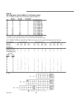
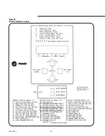
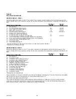
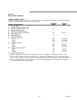
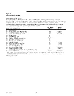
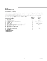
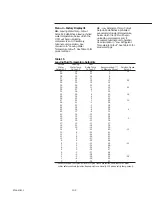
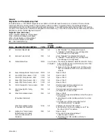
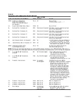
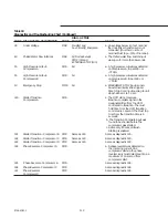
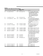
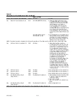
displayed. See Figure 52 for setpoint
ranges.
Options are also selected using the SET
POINT UP and SET POINT DOWN keys.
Use the SET POINT UP key to select the
“Enable” option and the letter “E” will
appear on the display. Use the SET
POINT DOWN key to select the
“Disable” option and the letter “d” will
be displayed. Certain items in Menus 4
and 5 will be integers with various
endpoints and units. See Figure 52.
Menu 0 – Operating Display
A
- Operating Code: This is the current
unit operating status, e.g. A 74, which,
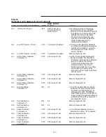
as shown in Figure 53, is Run:Normal.
b
- Last Diagnostic Code: The last
diagnostic detected by the UCM is
stored and can be seen by displaying
this I item.
C
- Other Diagnostics: All diagnostics
detected by the UCM will be stored in
preprescribed code number sequence,
as shown in Figure 53, rather than the
order in which they occurred. All
flashing codes found under this item
are currently active or “Latched”
diagnostics. For additional information,
see “Menus”.
Diagnostics will be stored only once,
even though the diagnostic may have
occurred several times. There is no
chronological sequence to the
diagnostics that may be in the “C”
menu item.
d
- Active Chilled Water Setpoint: The
setpoint (display only) to which the
chiller is controlling. This may be the
same as the Front Panel Chilled water
Setpoint (code 10 in Menu 1), but it
may also be a setpoint that is being
reset or loaded from a remote
controller, such as a Tracer, multiple-
machine controller, or a remote display
panel.
E
- Evap. Entering Water Temp.: The
temperature of the water as measured
by the evaporator entering water
temperature sensor. F - Evap. Leaving
Water Temp.: The temperature of the
water as measured by the evaporator
leaving water temperature sensor.
L
- Active Current Limit Setpoint: The
current limit setpoint (display only) to
which the chiller is controlled. This may
be the same as the Front Panel Current
Limit setpoint (code 13 in Menu 1), but
it may also be a setpoint that was
loaded from a remote controller, such
as a Tracer, multiple-machine
controller.
Menu 1 – Service #1 Display
10
- Front Panel Chilled Water Setpoint:
The temperature selected at the UCM
for the desired chilled water.
11
- Design Delta Temp. Setpoint: The
difference between the entering and
leaving chilled water temperatures at
full load. This will be a function of GPM
through the evaporator.
12
- Differential To Start Setpoint: This
temperature, when added to the
leaving chilled water setpoint, is the
temperature at which the chiller will be
started.
Note:
1.5 F below chill water setpoint,
the UCM will initiate an integrator to
shut off the last compressor on a
decrease in cooling load.
13
- Front Panel Current Limit Setpoint,
The percent of current limit selected at
the UCM for the system. See
discussion in “Current Limit Setpoint”.
14
- Outdoor Air Temperature
(Optional): The ambient temperature as
measured by an outdoor temperature
sensor.
15
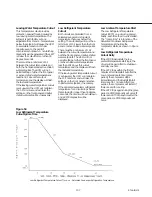
- Low Ambient Lockout (Optional): If
the unit is installed with optional
Outdoor Air Temperature Sensor, the
entry in this code will enable or disable
the setpoint in code 16. See discussion
in “Low Ambient Lockout”.
16
- Low Amb. Lockout Setpoint
(Optional): The temperature of the
outside air below which the unit will
not be permitted to operate. See
discussion in “Low Ambient Lockout”.
17
- Cond. Entering Wtr. Temp.: Not
applicable, with this air-cooled
condenser unit.
18
- Cond. Leaving Wtr. Temp.: Not
applicable, with this air- cooled
condenser unit.
19
- Service Pumpdown: Must be
manually “Enabled” by service
personnel from the UCM display. The
unit must be in STOP/RESET and
service pumpdown can be performed
only once for every power-up of the
UCM. Restart inhibit will be ignored,
the EXV will be prepositioned (20
seconds) and the compressor selected
will start and run for one minute.
Manual closing of the liquid line angle
valve will be required.
Caution: Do not pumpdown
compressor more than once.
1A
-Circuit Lockout: Allows service
personnel to set a lockout, preventing a
circuit from operating. With the display
indicating the number of the circuit to
be locked out, change the display to
“E” for circuit lockout. Once circuit
lockout is enabled, the circuit will
remain locked out even through a reset
or power down. Entering a “d” will
return the circuit to operational status.
1b
- Circuit Diagnostic Reset: Allows
service personnel to reset a Circuit
Manual Reset (CMR) diagnostic
without having to terminate operation
of the entire chiller via the STOP/RESET
switch. With the display indicating the
number of the circuit to be reset,
change the display to “E” to reset. After
reset, the display will automatically
return to “d”.
Summary of Contents for RTAA-130
Page 2: ... American Standard Inc 1991 ...
Page 8: ...8 RTAA IOM 3 ...
Page 24: ...24 RTAA IOM 3 ...
Page 50: ...50 RTAA IOM 3 Figure 30 Refrigerant Circuit Identification ...
Page 52: ...52 RTAA IOM 3 Figure 31 Remote Evaporator Piping Example ...
Page 59: ...59 RTAA IOM 3 Continued from Previous Page See Notes on Next Page ...
Page 63: ...63 RTAA IOM 3 Continued from Previous Page See Notes on Page 61 ...
Page 65: ...65 RTAA IOM 3 Continued from Previous Page See Notes on Page 61 ...
Page 76: ...76 RTAA IOM 3 ...
Page 92: ...92 RTAA IOM 3 Figure 51 Operator Interface Controls ...
Page 120: ...120 RTAA IOM 3 ...
Page 127: ...127 RTAA IOM 3 Continued from Previous Page 2307 1566C ...
Page 128: ...128 RTAA IOM 3 Figure 57 Unit Sequence of Operation RTAA 130 to 200 Tons 2306 9122A ...
Page 132: ...132 RTAA IOM 3 Figure 58 Operator s Log ...
Page 138: ...138 RTAA IOM 3 ...

