101
RTAA-IOM-3
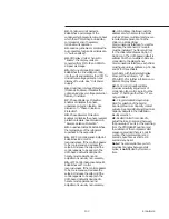
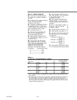
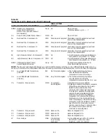
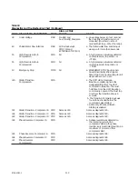
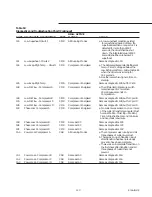
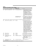
Menu 2 - Service #2 Display
20
- Compressor Mode: The current
compressor operating status, as shown
in Figure 53, will be displayed when
this menu item is selected.
21
- Compressor Suction Rfgt.
Temperature: Temperature as read by
the suction temperature sensor (see
Figure 40).
22
- Saturated Evaporator Rfgt
Temperature: Temperature as read by
the saturated evaporator temperature
sensor (see Figure 40).
23
- Evaporator Refrigerant Pressure:
The pressure displayed is the
evaporator refrigerant temperature
converted to an R-22 pressure. Units
are PSIG (Kilopascal gauge), referenced
to sea level (14.6960 psia or 101.3289
KPa absolute).
24
- Saturated Condenser Rfgt
Temperature: Temperature as read by
the saturated condensing temperature
sensor (see Figure 40).
25
- Condenser Refrigerant Pressure:
The pressure displayed is the
condenser refrigerant temperature
converted to an R-22 pressure. Units
are PSIG (Kilopascal gauge), referenced
to sea level (14.6960 psia or 101.3289
KPa absolute).
26
- EXV Test: EXV test will be initiated
when the unit is in STOP/RESET and
EXV Test is set to the “Enable” mode.
See “Electronic Expansion Valve (EXV)
Test’. Mode will automatically be reset
to “disable” upon completion of the
test.
27
- Compressor % RLA: The
percentage of Rated Load Amps on the
highest leg of the compressor motor.
See discussion in “Current Overload
Protection”.
28
- % Line Volts (Optional): If the unit
is installed with the optional over/under
voltage transformer, the UCM will
display the percentage value of line
volts as based on the nominal line
voltage set in Menu 4, Item 45.
29
- Compressor Starts (Optional): This
item serves as a non-resettable, non-
volatile accumulator of compressor
starts and is referenced by the UCM to
determine balancing of compressor
starts.
2A
- Compressor Hours (Optional):
This item serves as a non-resettable,
non-volatile accumulator of
compressor hours and is referenced by
the UCM to determine balancing of
compressor hours.
2b
- Compressor Test: Allows service
personnel to start a compressor and
check its operation. This eliminates the
time of waiting for the UCM lead/lag
function or load demand to start a
compressor. With the display indicating
the number of the circuit to be started,
change the display to “E” to start the
compressor on that circuit. After start,
the display will automatically return to
“d” and the UCM will resume its lead/
lag function of compressor control.
Menu 3 - Auxiliary Options
30
- External Chilled Water Setpoint:
Enables or disables chilled water
setpoint from an external control
system. See discussion in “Leaving
Chilled Water Temperature Control”.
31
- External Current Limit Setpoint:
Enables or disables current limit
setpoint for the system from an
external control system. See discussion
in “Current Limit Setpoint”.
32
- Ice Making Control: Enables or
disables the unit, when commanded by
a contact closure, to run fully loaded
and to stop, once ice termination
setpoint has been reached, e.g. ice
storage applications.
33
- Active Ice Termination Setpoint:
The selected temperature, from a
remote controller, such as a Tracer,
multiple-machine controller, or a
remote display panel, at which to
terminate the ice building mode, based
on the evaporator entering water
temperature. If no remote controllers
are connected, this setpoint should
agree with the Front Panel ice
termination setpoint. During normal
operation, this menu item will display
dashes, e.g. “33 -”.
34
- Front Panel Ice Termination
Setpoint: Established the temperature
of the entering chilled water at which
ice making is terminated. This setpoint
is the active setpoint when the chiller is
in the AUTO/LOCAL, ice mode.
35
- Return Reset: Enables or disables
Return CWR, based on the current
Delta-T across the evaporator (e.g:
Entering Chilled Water Temp. - Leaving
Chilled Water Temp.).
36
- Zone Reset: Enables or disables
Zone CWR, based on a zone
temperature sensor.
37
- Outdoor Reset: Enables or disables
Outdoor CWR, based on an outdoor
temperature sensor.
38
- Reset Ratio Setpoint: The reset
ratio, as a percent, to be used by the
UCM to calculate a reset chilled water
setpoint. See discussion in “Chilled
Water Reset”.
39
- Start Reset Setpoint: The start
reset temperature to be used by the
UCM to calculate a reset chilled water
setpoint. See discussion in “Chilled
Water Reset”.
3A
- Maximum Reset Setpoint: The
maximum reset temperature to be
used by the UCM to calculate a reset
chilled water setpoint. See discussion
in “Chilled Water Reset”.
3b
- External Circuit Lockout: When
enabled, individual circuit operation is
controlled by a remote, customer
specified/installed contact closure. See
External Circuit Lockout -Circuit #1 and
External Circuit Lockout -Circuit #2 in
the Installation - Electrical section.
Summary of Contents for RTAA-130
Page 2: ... American Standard Inc 1991 ...
Page 8: ...8 RTAA IOM 3 ...
Page 24: ...24 RTAA IOM 3 ...
Page 50: ...50 RTAA IOM 3 Figure 30 Refrigerant Circuit Identification ...
Page 52: ...52 RTAA IOM 3 Figure 31 Remote Evaporator Piping Example ...
Page 59: ...59 RTAA IOM 3 Continued from Previous Page See Notes on Next Page ...
Page 63: ...63 RTAA IOM 3 Continued from Previous Page See Notes on Page 61 ...
Page 65: ...65 RTAA IOM 3 Continued from Previous Page See Notes on Page 61 ...
Page 76: ...76 RTAA IOM 3 ...
Page 92: ...92 RTAA IOM 3 Figure 51 Operator Interface Controls ...
Page 120: ...120 RTAA IOM 3 ...
Page 127: ...127 RTAA IOM 3 Continued from Previous Page 2307 1566C ...
Page 128: ...128 RTAA IOM 3 Figure 57 Unit Sequence of Operation RTAA 130 to 200 Tons 2306 9122A ...
Page 132: ...132 RTAA IOM 3 Figure 58 Operator s Log ...
Page 138: ...138 RTAA IOM 3 ...

