104
RTAA-IOM-3
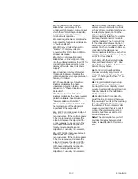
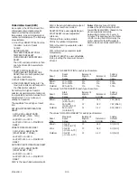
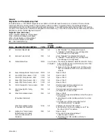
Menu 5 – Factory Display #2
50
- Number of Compressors: Set to
the number of compressor installed in
the unit.
51
- Compressor Tons: Set to the rating
in tons, of the each installed
compressor. See Table 2.
52
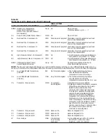
- Low Water Temperature EXV Gain
Compensation: Set to “E” if the unit
will ever operate with a leaving chilled
water temperature of 40 F or less.
53
- Fan Control: Set to “E”.
54
- Fans Per Circuit: Establishes the
number of fans installed on each
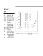
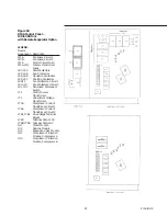
circuit. See Figures 45 and 46.
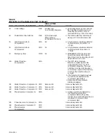
55
- Reduced Inrush Starting: Set to
“d” if across-the-line wiring or to “E” if
Wye-Delta wiring.
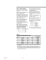
56
- Compressor Current Overload
Setting: Establishes the compressor
motor current overload setting, which
must agree with the DIP Switch
settings on the corresponding
compressor modules. See Table 16.
Compressor
Compressor Module
A ................................. 1U4
B .................................. 1U5
C .................................. 1U6
D ................................. 1U7
57
- GP Compressor Unit: This menu
item must be set to “d”. The unit is not
to be operated unless a “d” is
displayed in this item.
58
- Low Ambient, Half Airflow Fan
(Halfpitch Blades on Lead Fan(s): Set
this menu item per the following unit
selections
RTAA 130 - 200 Standard Ambient = d
RTAA 130 - 200 Low Ambient
= E
RTAA 240 - 400 All
= E
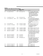
59
- LATSM: Set this menu item to “d”.
5A
- NNS: Set this menu item to “d”.
5b
- Number of EXV Valves per Circuit:
Set this menu item per the following
unit selections
RTAA 130 - 200 Circuit 1 = 1
Circuit 2 = 1
RTAA 240 - 300 Circuit 1 = 2
Circuit 2 = 1
RTAA 340 - 400 Circuit 1 = 2
Circuit 2 = 2
5C
- Future Option: Set this menu item
to “d” for both Circuit #1 and Circuit #2.
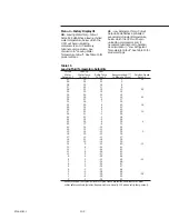
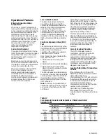
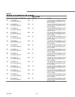
Table 16
Compressor Overload DIP Switch Settings
Overload Setting
Compressor
CT
DIP Sw/Decimal**
Tons
Volts.Hz
RLA
Ext*
12345
70
200/230.60
280
-05
00100/04
460.60
122
-02
10000/16
575.60
98
-01
11110/30
85
200/230.60
306
-05
01011/11
460.60
133
-02
10110122
575.60
107
-02
00110/06
100
200/230.60
375
-05
11010/26
460.60
163
-03
10000/16
575.60
131
-02
10110122
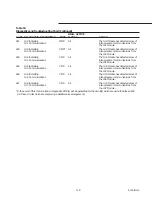
*The CT base part number is X13580253. The numbers in this column are suffixes to the
base number.
**On the DIP switch, 1= ON, O= OFF. The decimal number is the setting Menu Item 56. The
DIP switch setting and the decimal display of Item 56 comprise a redundant overload
setting. If the values are not set to match, the related compressor(s) will continue to run,
but a diagnostic will be initiated, both settings will be ignored, and the UCM will use the
lowest possible trip setting value.
Summary of Contents for RTAA-130
Page 2: ... American Standard Inc 1991 ...
Page 8: ...8 RTAA IOM 3 ...
Page 24: ...24 RTAA IOM 3 ...
Page 50: ...50 RTAA IOM 3 Figure 30 Refrigerant Circuit Identification ...
Page 52: ...52 RTAA IOM 3 Figure 31 Remote Evaporator Piping Example ...
Page 59: ...59 RTAA IOM 3 Continued from Previous Page See Notes on Next Page ...
Page 63: ...63 RTAA IOM 3 Continued from Previous Page See Notes on Page 61 ...
Page 65: ...65 RTAA IOM 3 Continued from Previous Page See Notes on Page 61 ...
Page 76: ...76 RTAA IOM 3 ...
Page 92: ...92 RTAA IOM 3 Figure 51 Operator Interface Controls ...
Page 120: ...120 RTAA IOM 3 ...
Page 127: ...127 RTAA IOM 3 Continued from Previous Page 2307 1566C ...
Page 128: ...128 RTAA IOM 3 Figure 57 Unit Sequence of Operation RTAA 130 to 200 Tons 2306 9122A ...
Page 132: ...132 RTAA IOM 3 Figure 58 Operator s Log ...
Page 138: ...138 RTAA IOM 3 ...

