114
RTAA-IOM-3
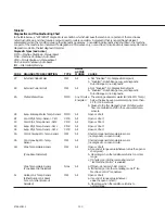
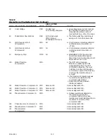
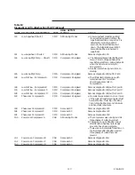
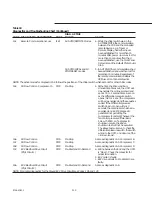
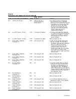
Table 18
Diagnostics and Troubleshooting Chart (Continued)
DIAG. ACTIVE
CODE DIAGNOSTIC DESCRIPTION
TYPE
MODES
CAUSE
1A4
Remote Communications Loss
IFW
All AUTO/REMOTE Modes
a. While the chiller switch was in the
AUTO/REMOTE the communication
between the CSR and the connected
remote device, e.g. a Tracer or
Remote Display, had either never
been established for more than 15
minutes after power up or was lost for
more than 15 minutes after it had
been established; use the Front Panel
Setpoints and the Default Chiller Auto/
Stop.
All AUTO/LOCAL and all
b. In AUTO/LOCAL communications had
STOP/RESET modes
been established and was then lost for
more than 15 minutes. Regardless of
the remote communication status the
UCM uses Front Panel setpoints.
NOTE: The active modes for diagnostic 1A4 follows the positions of the chiller switch which account for other chiller codes.
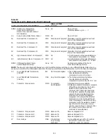
1A5
Oil Flow Control - Compressor A
CMR
Pre-Stop
a. At the time the 20 second Run:
Unload time times out, the UCM will
de-energize the oil line solenoid and
set a 10+ or -1 second timer. As soon
as the differential pressure switch
opens (0.8 to 1.2 sec.) the compressor
will be de-energized and the sequence
ended. If the differential pressure
switch does not open within 10
seconds, the compressor shall be de-
energized and a CMR diagnostic
generated not permitting the
compressor to restart. Whenever the
fan control pressure differential is
below 70 PSID, or if a diagnostic
shutdown occurs, the above
shutdown test will not be executed.
The above test will serve to check the
differential pressure switch, the switch
wiring to the UCM, and closure of the
oil line solenoid.
1A6
Oil Flow Control -
CMR
Pre-Stop
Same as diagnostic 1A5. Compressor B
1A7
Oil Flow Control -
CMR
Pre-Stop
Same as diagnostic 1A5. Compressor C
1A8
Oil Flow Control -
CMR
Pre-Stop
Same as diagnostic 1A5. Compressor D
1A9
EXV Electrical Drive Circuit
CMR
Pre-Start and On Demand
a. Wiring between the EXV and the UCM
(Rfgt. Circuit 1)
is “Open”. Check the connector for
proper termination.
b. EXV motor is faulty.
c. EXV drive circuits on Module 1U3 are
faulty.
1AA
EXV Electrical Drive Circuit
CMR
Pre-Start and On Demand
Same as diagnostic 1A9.
(Rfgt. Circuit 2)
NOTE: For similar diagnostics for the Slaved EXV Drive Circuits see Codes 1 db and 1 dC.
Summary of Contents for RTAA-130
Page 2: ... American Standard Inc 1991 ...
Page 8: ...8 RTAA IOM 3 ...
Page 24: ...24 RTAA IOM 3 ...
Page 50: ...50 RTAA IOM 3 Figure 30 Refrigerant Circuit Identification ...
Page 52: ...52 RTAA IOM 3 Figure 31 Remote Evaporator Piping Example ...
Page 59: ...59 RTAA IOM 3 Continued from Previous Page See Notes on Next Page ...
Page 63: ...63 RTAA IOM 3 Continued from Previous Page See Notes on Page 61 ...
Page 65: ...65 RTAA IOM 3 Continued from Previous Page See Notes on Page 61 ...
Page 76: ...76 RTAA IOM 3 ...
Page 92: ...92 RTAA IOM 3 Figure 51 Operator Interface Controls ...
Page 120: ...120 RTAA IOM 3 ...
Page 127: ...127 RTAA IOM 3 Continued from Previous Page 2307 1566C ...
Page 128: ...128 RTAA IOM 3 Figure 57 Unit Sequence of Operation RTAA 130 to 200 Tons 2306 9122A ...
Page 132: ...132 RTAA IOM 3 Figure 58 Operator s Log ...
Page 138: ...138 RTAA IOM 3 ...

