22
RTAA-IOM-3
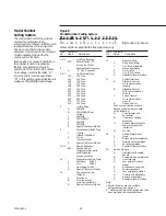
Figure 8
Model Number Coding System
RTA A 200 G X B0 1 A 0 D 0 B D E G
0
1
2
123
4 567 8
9
01 2 3
4 5
6 7 8 9 0
(Digit position for above)
Where digits are assigned the following meanings:
Digit
Character
No.
Value
Description
1, 2, 3
Unit Type/Function
RTA
Rotary (Series “R”)
Air Cooled Chiller
4
Development Sequence
A
“A” Dev. Sequence
5, 6, 7
Unit Nominal Tons
130
130 Tons
140
140 Tons
155
155 Tons
170
170 Tons
185
185 Tons
200
200 Tons
240
240 Tons
270
270 Tons
300
300 Tons
340
340 Tons
370
370 Tons
400
400 Tons
8
Unit Voltage
D
380/60/3
G
200-230/60/3 Dual
Voltage
1
346/50/3
K
380-415/50/3
4
460/60/3
5
575/60/3
S
Special Customer Option
9
Compressor Starter Type
Y
Y-Delta
(Closed Transition)
X
X-Line
(Across the line)
S
Special Customer Option
10, 11
Design Sequence
BO
Second design.
Increment when parts
are affected for
service purposes.
12
Evaporator Leaving Temp.
1
Standard
40-60 F
2
Low
20-40 F
3
Ice making 20-60 F
S
Special Customer Option
13
Condenser Coil Fin
Material
A
Aluminum
B
Aluminum with
corrosion protection
S
Special Customer Option
Digit
Character
No.
Value
Description
14
Agency Listing
0
No agency listing
1
U.L. listed - Standard
where applicable
2
C.S.A. listed
3
*U.L./C.S.A. listed
S
Special Customer Option
15
Control Interface
A
Standard Control
No communication
module
B
Standard Control
With communication
module
C
Deluxe Control
No communication
module
D
Deluxe Control
With communication module
Deluxe control option consists
of the following:
A -
Cycle counter and
hour meter
B -
Under/over voltage
protection
C -
Remote alarm contacts
and compressor run
indication
D -
% volts
16
Chilled Water Reset
0
None
1
Return water temperature
2
Outside air temperature
3
Zone temperature
S
Special Customer Option
17+
Add on Options
A
Architectural louvered
panels
B
Control power transformer
C
Heat recovery
D
Low ambient lockout
sensor
E
Suction service valves
F
Power disconnect
G
Low ambient operation
H
*Unit sound attenuator
I
Remote evaporator
S
Special Customer Option
Note:
1. Digits 17 and on may be multiple,
independent add on options.
2. * Denotes that this option assignment has
been made but is not available now
Model Number
Coding System
The model numbers for the outdoor
unit and the compressors are
comprised of numbers and letter which
represent features of the equipment.
Shown on the chart in Figure 8 are
samples of typical unit and compressor
model numbers, followed by the
coding system for each.
Each position, or group of positions, in
the number is used to represent a
feature. For example, in Figure 8,
position 08 of the unit model number,
Unit Voltage, contains the letter “G”.
From the chart, it can be seen that a
“G” in this position means that the unit
voltage is 200-230/60/3 dual voltage.
Summary of Contents for RTAA-130
Page 2: ... American Standard Inc 1991 ...
Page 8: ...8 RTAA IOM 3 ...
Page 24: ...24 RTAA IOM 3 ...
Page 50: ...50 RTAA IOM 3 Figure 30 Refrigerant Circuit Identification ...
Page 52: ...52 RTAA IOM 3 Figure 31 Remote Evaporator Piping Example ...
Page 59: ...59 RTAA IOM 3 Continued from Previous Page See Notes on Next Page ...
Page 63: ...63 RTAA IOM 3 Continued from Previous Page See Notes on Page 61 ...
Page 65: ...65 RTAA IOM 3 Continued from Previous Page See Notes on Page 61 ...
Page 76: ...76 RTAA IOM 3 ...
Page 92: ...92 RTAA IOM 3 Figure 51 Operator Interface Controls ...
Page 120: ...120 RTAA IOM 3 ...
Page 127: ...127 RTAA IOM 3 Continued from Previous Page 2307 1566C ...
Page 128: ...128 RTAA IOM 3 Figure 57 Unit Sequence of Operation RTAA 130 to 200 Tons 2306 9122A ...
Page 132: ...132 RTAA IOM 3 Figure 58 Operator s Log ...
Page 138: ...138 RTAA IOM 3 ...

