44
RTAA-IOM-3
Water Treatment
Using untreated or improperly treated
water in these units may result in
inefficient operation and possible tube
damage. Consult a qualified water
treatment specialist to determine
whether treatment is needed. The
following disclamatory label is
provided on each RTAA unit:
Customer Note
The use of improperly treated or
untreated water in this equipment may
result in scaling, erosion, corrosion,
algae or slime. The services of a
qualified water treatment specialist
should be engaged to determine what
treatment, if any, is advisable. The
Trane Company warranty specifically
excludes liability for corrosion, erosion
or deterioration of Trane equipment.
Trane assumes no responsibilities for
the results of the use of untreated or
improperly treated water, or saline or
brackish water.
Caution: Do not use untreated or
improperly treated water.
Equipment damage may occur.
Water Pressure Gauges
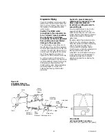
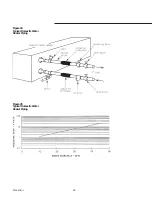
Install field-supplied pressure gauges
(with manifolds, whenever practical) as
shown in Figure 22. Locate pressure
gauges or taps in a straight run of pipe;
avoid placement near elbows, etc. Be
sure to install the gauges at the same
elevation on each shell if the shells
have opposite-end water connections.
To read manifolded pressure gauges,
open one valve and close the other
(depending upon the reading desired).
This eliminates errors resulting from
differently calibrated gauges installed
at unmatched elevations.
Water Pressure Relief Valves
Install a water pressure relief valve in
the evaporator inlet piping between the
evaporator and the inlet shutoff valve,
as shown in Figure 22. Water vessels
with close-coupled shutoff valves have
a high potential for hydrostatic
pressure buildup on a water
temperature increase. Refer to
applicable codes for relief valve
installation guidelines.
Caution: To prevent shell damage,
install pressure relief valves in the
evaporator water system.
Freeze Protection
If the unit will remain operational at
subfreezing ambient temperatures, the
chilled water system must be protected
from freezing, following the steps listed
below
1. Heat tape is factory-installed on the
packaged unit evaporator and will
protect it from freezing in ambient
temperatures down to -20 F.
2. Install heat tape on all water piping,
pumps, and other components that
may be damaged if exposed to
freezing temperatures. Heat tape
must be designed for low ambient
temperature applications. Heat tape
selection should be based on the
lowest expected ambient
temperature.
3. Add a non-freezing, low temperature,
corrosion inhibiting, heat transfer
fluid to the chilled water system. The
solution must be strong enough to
provide protection against ice
formation at the lowest anticipated
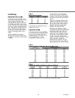
ambient temperature. Refer to Table
1 for evaporator water storage
capacities.
Note: Use of glycol type antifreeze
reduces the cooling capacity of the unit
and must be considered in the design
of the system specifications.
Summary of Contents for RTAA-130
Page 2: ... American Standard Inc 1991 ...
Page 8: ...8 RTAA IOM 3 ...
Page 24: ...24 RTAA IOM 3 ...
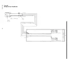
Page 50: ...50 RTAA IOM 3 Figure 30 Refrigerant Circuit Identification ...
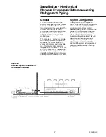
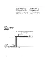
Page 52: ...52 RTAA IOM 3 Figure 31 Remote Evaporator Piping Example ...
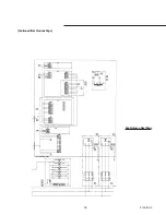
Page 59: ...59 RTAA IOM 3 Continued from Previous Page See Notes on Next Page ...
Page 63: ...63 RTAA IOM 3 Continued from Previous Page See Notes on Page 61 ...
Page 65: ...65 RTAA IOM 3 Continued from Previous Page See Notes on Page 61 ...
Page 76: ...76 RTAA IOM 3 ...
Page 92: ...92 RTAA IOM 3 Figure 51 Operator Interface Controls ...
Page 120: ...120 RTAA IOM 3 ...
Page 127: ...127 RTAA IOM 3 Continued from Previous Page 2307 1566C ...
Page 128: ...128 RTAA IOM 3 Figure 57 Unit Sequence of Operation RTAA 130 to 200 Tons 2306 9122A ...
Page 132: ...132 RTAA IOM 3 Figure 58 Operator s Log ...
Page 138: ...138 RTAA IOM 3 ...

