69
RTAA-IOM-3
Interconnecting Wiring
Chilled Water Pump Interlock
and External Auto/Stop for
Model RTAA Air-Cooled
Series R CenTraVac
Caution: The following must be
adhered to or equipment damage
may occur.
The Model RTAA Series R chiller
requires a minimum of two field-
supplied control inputs:
•
Chilled water pump interlock (TB3-1, -
2 on the 1U1 board).
•
External Auto/Stop (T133-3, -4 on the
1U1 board)
When there is a command to shut
down the chilled water system, the
chilled water pump is required to
operate for a minimum of one minute
after the External AUTO/STOP gives
the shutdown command.
Normally, when the compressors are
terminating a cycle (via chiller Stop/
Reset switch, loss of load, Low
Ambient Run Inhibit or External Auto/
Stop), the controller will initiate the
“Run:Unload” mode. This operating
mode energizes the unload solenoid
for 20 seconds, to unload the
compressor so that it will be unloaded
for the next start-up. Then the master
oil solenoid is de-energized and closure
of the master oil solenoid is verified.
The entire process may take up to 40
seconds.
If the chilled water pump interlock is
used without the external Auto/Stop
input, the chiller will shut down
immediately upon the command for
shut down, without initiating the
“Run:Unload” mode. This is
considered a “non-friendly” shut down
and a “Machine Auto Reset” diagnostic
will be displayed on the LICK
Caution: The method in the
previous paragraph is not to be
used as a normal means of cycling
the chiller off, e.g. time clock,
building automation system, etc.
The proper method for cycling the
chiller off is to open a set of contact
between TB3-3, -4 on the 1U1 board
(External Auto/Stop). Then, following a
one minute delay, the chilled water
pump is cycled off. Chilled water flow
indication should be provided between
TB3-1, -2 on the 1U1 board, e.g. water
pump motor starter auxiliaries and/or
flow switch.
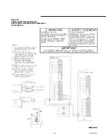
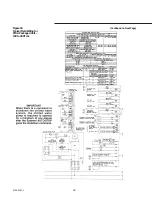
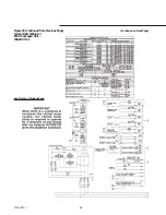
The wiring for this recommendation is
shown in the furnished electrical
schematics and connection diagrams.
Relay 5DL1 is a normally-open,
instantaneous close, timed open (1
min.) time delay relay. An alternative
solution is to provide proper
programming in a building automation
system.
Chilled Water Pump Interlock
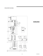
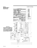
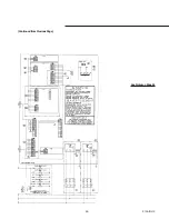
The installer must provide leads 520
and 521 from the chilled water pump
(5B1) starter auxiliary (5K1) to the
proper terminals of terminal strip 1U1
TB3 on the UCM, as shown in Figures
34 thru 36. Circuit requirement is 115
VAC, with minimum contact rating @
115 VAC of 6.9 VA inrush, 1.3 VA sealed.
Refer to the field diagrams which are
shipped with the unit.
The auxiliary contact of the chilled
water pump may be wired in series
with an optional flow switch, as shown.
The standard UCM provides internal
protection for the unit against loss of
chilled water flow. Also refer to
“Evaporator Flow Switch.”
External Auto/Stop Wiring
If the unit requires the Auto/Stop
function, the installer must provide
leads 522 and 523 from the remote
contacts (5K5, 5K21) to the proper
terminals of the terminal strip 1U1 TB3
on the UCM, as shown in Figures 34
thru 36.
The chiller will run normally when the
contacts are closed. When either
contact opens, the compressor(s), if
operating, will go to the RUN:UNLOAD
operating mode and cycle off. Unit
operation will be inhibited. Re-closure
of the contacts will permit the unit to
automatically return to normal
operation.
Circuit requirements are 2-wire, 115
VAC, with minimum contact rating @
115 VAC of 6.9 VA inrush, 1.3 VA sealed.
Refer to the field diagrams which are
shipped with the unit.
Summary of Contents for RTAA-130
Page 2: ... American Standard Inc 1991 ...
Page 8: ...8 RTAA IOM 3 ...
Page 24: ...24 RTAA IOM 3 ...
Page 50: ...50 RTAA IOM 3 Figure 30 Refrigerant Circuit Identification ...
Page 52: ...52 RTAA IOM 3 Figure 31 Remote Evaporator Piping Example ...
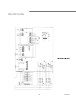
Page 59: ...59 RTAA IOM 3 Continued from Previous Page See Notes on Next Page ...
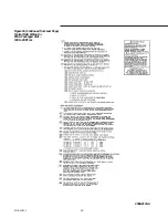
Page 63: ...63 RTAA IOM 3 Continued from Previous Page See Notes on Page 61 ...
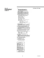
Page 65: ...65 RTAA IOM 3 Continued from Previous Page See Notes on Page 61 ...
Page 76: ...76 RTAA IOM 3 ...
Page 92: ...92 RTAA IOM 3 Figure 51 Operator Interface Controls ...
Page 120: ...120 RTAA IOM 3 ...
Page 127: ...127 RTAA IOM 3 Continued from Previous Page 2307 1566C ...
Page 128: ...128 RTAA IOM 3 Figure 57 Unit Sequence of Operation RTAA 130 to 200 Tons 2306 9122A ...
Page 132: ...132 RTAA IOM 3 Figure 58 Operator s Log ...
Page 138: ...138 RTAA IOM 3 ...

