82
RTAA-IOM-3
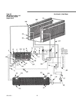
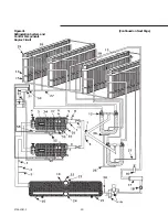
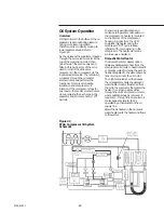
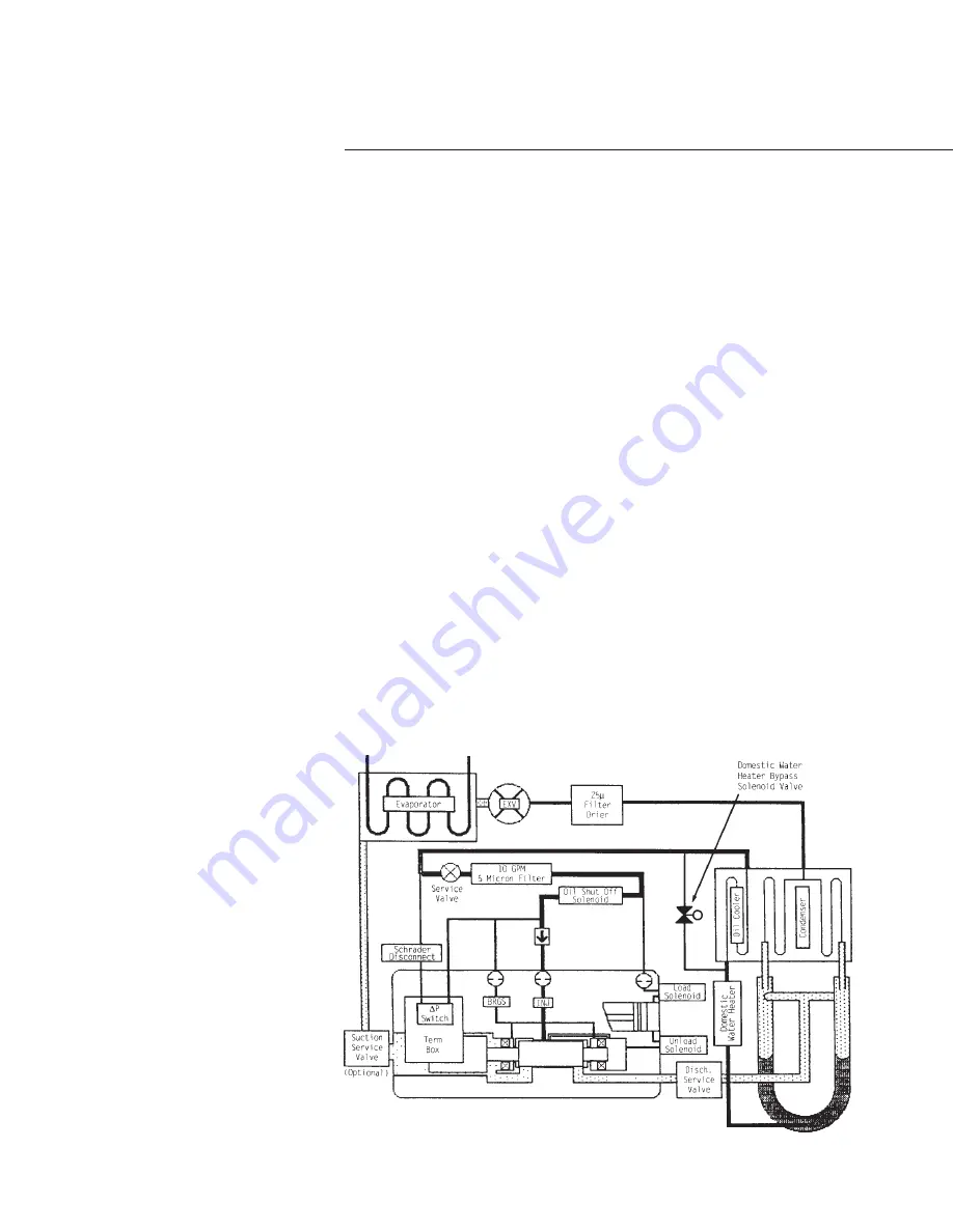
Figure 43
RTAA Compressor Oil System
Schematic
Oil System Operation
Overview
Oil that collects in the bottom of the oil
separator is at condensing pressure
during compressor operation;
therefore, oil is constantly moving to
lower pressure areas. Refer to
Figure 43.
As the oil leaves the separator, it passes
through the air-cooled oil cooler at the
top of the condensing coils. It then
goes through the service valve and
filter. At this point, some of the oil is
used to control the slide valve
movement in the compressor, via the
load/unload solenoids. The remaining
oil passes through the oil master
solenoid valve and performs the
functions of compressor bearing
lubrication and compressor oil
injection. If the compressor stops for
any reason, the master solenoid valve
closes, isolating the oil charge in the
separator and oil cooler during “off”
periods.
To ensure proper lubrication and
minimize refrigerant condensation in
the compressor, a heater is mounted
on the bottom of the compressor
housing. A signal from the UCM
energizes this heater during the
compressor “Off” cycle to keep
refrigerant from condensing in the
compressor. The heater element is
continuously energized.
Domestic Water Heater
The Domestic Water Heater option
utilizes available waste heat from the
compressor oil circuit, to heat domestic
or process water. Normally, the excess
heat is dissipated to the atmosphere by
fans moving air over the oil cooler.
The high temperature oil that leaves
the oil separator enters the domestic
water heater. Heat is transferred from
the oil to the cool water that enters the
heater. The oil then passes either
through the unit’s air-cooled oil cooler,
where additional heat is removed, if
required, or through the air-cooled oil
cooler bypass solenoid, that is
operated by a thermostat on the oil
supply line.
Water that is heated in the domestic
water heater exits the heater and flows
to the system.
Summary of Contents for RTAA-130
Page 2: ... American Standard Inc 1991 ...
Page 8: ...8 RTAA IOM 3 ...
Page 24: ...24 RTAA IOM 3 ...
Page 50: ...50 RTAA IOM 3 Figure 30 Refrigerant Circuit Identification ...
Page 52: ...52 RTAA IOM 3 Figure 31 Remote Evaporator Piping Example ...
Page 59: ...59 RTAA IOM 3 Continued from Previous Page See Notes on Next Page ...
Page 63: ...63 RTAA IOM 3 Continued from Previous Page See Notes on Page 61 ...
Page 65: ...65 RTAA IOM 3 Continued from Previous Page See Notes on Page 61 ...
Page 76: ...76 RTAA IOM 3 ...
Page 92: ...92 RTAA IOM 3 Figure 51 Operator Interface Controls ...
Page 120: ...120 RTAA IOM 3 ...
Page 127: ...127 RTAA IOM 3 Continued from Previous Page 2307 1566C ...
Page 128: ...128 RTAA IOM 3 Figure 57 Unit Sequence of Operation RTAA 130 to 200 Tons 2306 9122A ...
Page 132: ...132 RTAA IOM 3 Figure 58 Operator s Log ...
Page 138: ...138 RTAA IOM 3 ...

