83
RTAA-IOM-3
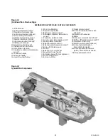
Oil Separator
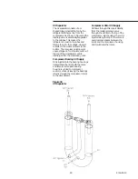
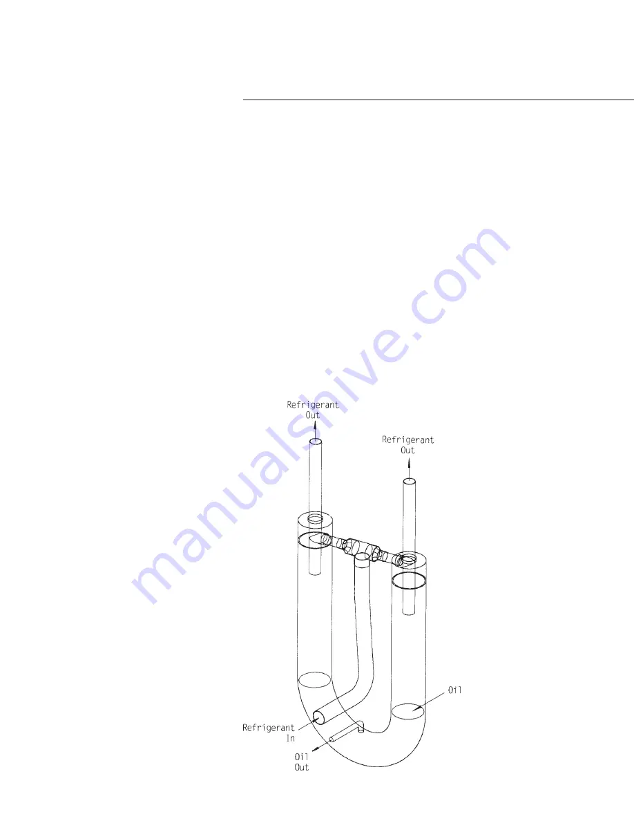
The oil separator consists of a U-
shaped tube, joined at the top by the
refrigerant discharge line from the
compressor. As shown in Figure 44, the
discharge line is essentially tangential
to the U-tubes. This causes the
refrigerant to swirl in the tubes and
throws the oil to the outside, where it
collects on the walls and flows to the
bottom. The compressed refrigerant
vapor, stripped of oil droplets, exits out
the top of the oil separator and is
discharged into the condensing coils.
Compressor Bearing Oil Supply
Oil is injected into the bearing housings
located at each end of both the male
and female rotors. Each bearing
housing is vented to compressor
suction, so that oil leaving the bearings
returns through the compressor rotors
to the oil separator.
Compressor Rotor Oil Supply
Oil flows through this circuit directly
from the master solenoid valve
through the oil filter to the top of the
compressor rotor housing. There it is
injected along the top of the rotors to
seal clearance spaces between the
rotors and the compressor housing
and to lubricate the rotors.
Figure 44
Oil Separator
Summary of Contents for RTAA-130
Page 2: ... American Standard Inc 1991 ...
Page 8: ...8 RTAA IOM 3 ...
Page 24: ...24 RTAA IOM 3 ...
Page 50: ...50 RTAA IOM 3 Figure 30 Refrigerant Circuit Identification ...
Page 52: ...52 RTAA IOM 3 Figure 31 Remote Evaporator Piping Example ...
Page 59: ...59 RTAA IOM 3 Continued from Previous Page See Notes on Next Page ...
Page 63: ...63 RTAA IOM 3 Continued from Previous Page See Notes on Page 61 ...
Page 65: ...65 RTAA IOM 3 Continued from Previous Page See Notes on Page 61 ...
Page 76: ...76 RTAA IOM 3 ...
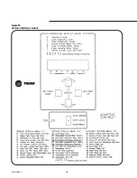
Page 92: ...92 RTAA IOM 3 Figure 51 Operator Interface Controls ...
Page 120: ...120 RTAA IOM 3 ...
Page 127: ...127 RTAA IOM 3 Continued from Previous Page 2307 1566C ...
Page 128: ...128 RTAA IOM 3 Figure 57 Unit Sequence of Operation RTAA 130 to 200 Tons 2306 9122A ...
Page 132: ...132 RTAA IOM 3 Figure 58 Operator s Log ...
Page 138: ...138 RTAA IOM 3 ...

