91
RTAA-IOM-3
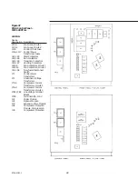
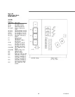
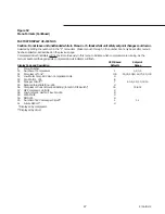
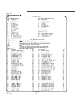
Figure 50
RTAA Control Panel –
130 to 200 Tons
with Remote Evaporator Option
LEGEND:
Device
Designation Description
1F1-6
Fan Fuses, Circuit 1
1F7-12
Fan Fuses, Circuit 2
1F15
Control Circuit Fuse
1F16, 1F17
Primary Transformer
Fuses
1K1, 1K5
Start Contactors
1K2, 1K6
Run Contactors
1K4, 1K8
Transition Contactors
1K5, 1K7
Shorting Contactors
1K9-12
Fan Contactors, Circuit 1
1K13-16
Fan Contactors, Circuit 2
1S1, 1S2
Non-fused Disconnect
Switch
1T1
Control Power
Transformer
1T2
Under/Over Voltage
Transformer
1T3-5
Compressor Current
Transformer, Circuit 1
1T6-8
Compressor Current
Transformer, Circuit 2
1TB1, 1TB2
Line Voltage Terminal
Blocks
1TB3
Terminal Strip, 115 V
1TB8, 1TB9
Terminal Strip, 24 V
1U1
Chiller Module
1U2
Options Module
1U3
Expansion Valve Module
1U4
Compressor Protection
Module, Compressor A
1U5
Compressor Protection
Module, Compressor B
Summary of Contents for RTAA-130
Page 2: ... American Standard Inc 1991 ...
Page 8: ...8 RTAA IOM 3 ...
Page 24: ...24 RTAA IOM 3 ...
Page 50: ...50 RTAA IOM 3 Figure 30 Refrigerant Circuit Identification ...
Page 52: ...52 RTAA IOM 3 Figure 31 Remote Evaporator Piping Example ...
Page 59: ...59 RTAA IOM 3 Continued from Previous Page See Notes on Next Page ...
Page 63: ...63 RTAA IOM 3 Continued from Previous Page See Notes on Page 61 ...
Page 65: ...65 RTAA IOM 3 Continued from Previous Page See Notes on Page 61 ...
Page 76: ...76 RTAA IOM 3 ...
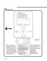
Page 92: ...92 RTAA IOM 3 Figure 51 Operator Interface Controls ...
Page 120: ...120 RTAA IOM 3 ...
Page 127: ...127 RTAA IOM 3 Continued from Previous Page 2307 1566C ...
Page 128: ...128 RTAA IOM 3 Figure 57 Unit Sequence of Operation RTAA 130 to 200 Tons 2306 9122A ...
Page 132: ...132 RTAA IOM 3 Figure 58 Operator s Log ...
Page 138: ...138 RTAA IOM 3 ...

