94
RTAA-IOM-3
Figure 52
Menu Formats (Continued)
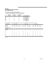
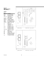
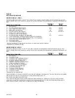
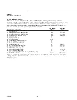
SERVICE #1 DISPLAY – MENU 1
Selected by setting the number 1 in the “P” menu item. The compressor circuit indicators will not be lit continuously in this
menu to indicate which compressors are running. As the menu is advanced, the appropriate compressor/circuit indicator will
flash.
UCM Based
Setpoint
Display Code and Description
Defaults
Range
P
Menu Number
10
Front Panel Chilled Water Setpoint
44 F
0 to 65 F
11
Design Delta Temperature Setpoint
10 F
4 to 30 F
12
Differential to Start Setpoint
2 F
2 to 30 F
13
Front Panel Current Limit Setpoint
120%
40 to 120%
14
Outdoor Air Temperature (Optional)
15
Low Ambient Lockout - d/E (Optional)
d
16
Low Ambient Lockout Setpoint - d/E (Optional)*
20 F
-20 to 40 F
17
Cond. Entering Water Temperature (Optional) RTAA Non Applicable
18
Cond. Leaving Water Temperature (Optional) RTAA = Non Applicable
19
Service Pumpdown d/E (Stop/Reset only)**
d
1A
Circuit Lockout d/E**
d
1b
Circuit Diagnostics Reset**
d
*Dashes are displayed for the setpoint when the Low Ambient Lockout (15) is disabled.
**Displayed by Compressor/Circuit
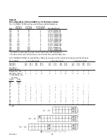
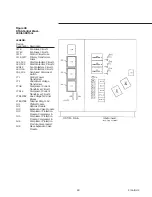
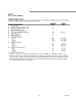
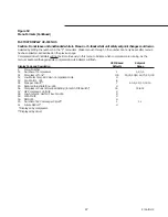
SERVICE #2 DISPLAY - MENU 2
Selected by setting the number 2 in the “P” menu item. Compressor/Circuit indicators shall not be lit continuously in this
menu to indicate which compressors are running. As the menu is advanced, the appropriate compressor/circuit indicator will
flash.
UCM Based
Setpoint
Display Code and Description
Defaults
Range
P
Menu Number
20
Compressor Mode*
21
Compressor Suction Refrigerant Temp.*
22
Compressor Evap. Refrigerant Temp.*
23
Evaporator Refrigerant Pressure*
24
Saturated Condenser Refrigerant Temp.*
25
Condenser Refrigerant Pressure*
26
EXV Test - d/E (Only in STOP/RESET)*
d
27
Compressor % RLA (Highest leg)*
28
% Line Volts (Optional)
29
Compressor Starts (Optional)*
2A
Compressor Hours (Optional)*
2b
Compressor Test d/E
d
*Displayed by compressor/circuit
Compressor Starts, Compressor Hours and % Line Volts will be displayed as dashes (e.g. “2A when this option is not installed.
After the EXV test has been completed, the “E” will be automatically reset to “d”.
See “Electronic Expansion Valve (EXV) Test”.
The Condenser Refrigerant Pressure and the Evaporator Refrigerant Pressure, displayed on the UCM, are the saturated
condenser and evaporator temperatures converted to R-22 pressure readings. The units are PSIG (Kilopascal gauge) and
referenced to an elevation of sea level or 14.6960 psia (101.3289 KPa absolute).
Summary of Contents for RTAA-130
Page 2: ... American Standard Inc 1991 ...
Page 8: ...8 RTAA IOM 3 ...
Page 24: ...24 RTAA IOM 3 ...
Page 50: ...50 RTAA IOM 3 Figure 30 Refrigerant Circuit Identification ...
Page 52: ...52 RTAA IOM 3 Figure 31 Remote Evaporator Piping Example ...
Page 59: ...59 RTAA IOM 3 Continued from Previous Page See Notes on Next Page ...
Page 63: ...63 RTAA IOM 3 Continued from Previous Page See Notes on Page 61 ...
Page 65: ...65 RTAA IOM 3 Continued from Previous Page See Notes on Page 61 ...
Page 76: ...76 RTAA IOM 3 ...
Page 92: ...92 RTAA IOM 3 Figure 51 Operator Interface Controls ...
Page 120: ...120 RTAA IOM 3 ...
Page 127: ...127 RTAA IOM 3 Continued from Previous Page 2307 1566C ...
Page 128: ...128 RTAA IOM 3 Figure 57 Unit Sequence of Operation RTAA 130 to 200 Tons 2306 9122A ...
Page 132: ...132 RTAA IOM 3 Figure 58 Operator s Log ...
Page 138: ...138 RTAA IOM 3 ...

