123
RTAA-IOM-3
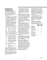
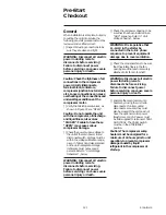
Unit Voltage Phasing
It is important that proper rotation of
the compressors be established before
the unit is started. Proper motor
rotation requires confirmation of the
electrical phase sequence of the power
supply. The motor is internally
connected for clockwise rotation with
the incoming power supply phased
A, B, C.
Basically, voltages generated in each
phase of a polyphase alternator or
circuit are called phase voltages. In a
three-phase circuit, three sine wave
voltages are generated, differing in
phase by 120 electrical degrees. The
order in which the three voltages of a
three-phase system succeed one
another is called phase sequence or
phase rotation. This is determined by
the direction of rotation of the
alternator. When rotation is clockwise
phase sequence is usually called
“‘ABC”, when counterclockwise,
“CBA”.
This direction may be reversed outside
the alternator by interchanging any two
of the line wires. It is this possible
interchange of wiring that makes a
phase sequence indicator necessary if
the operator is to quickly determine the
phase rotation of the motor.
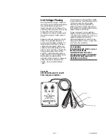
Proper compressor motor electrical
phasing can be quickly determined and
corrected before starting the unit. Use a
quality instrument, such as the
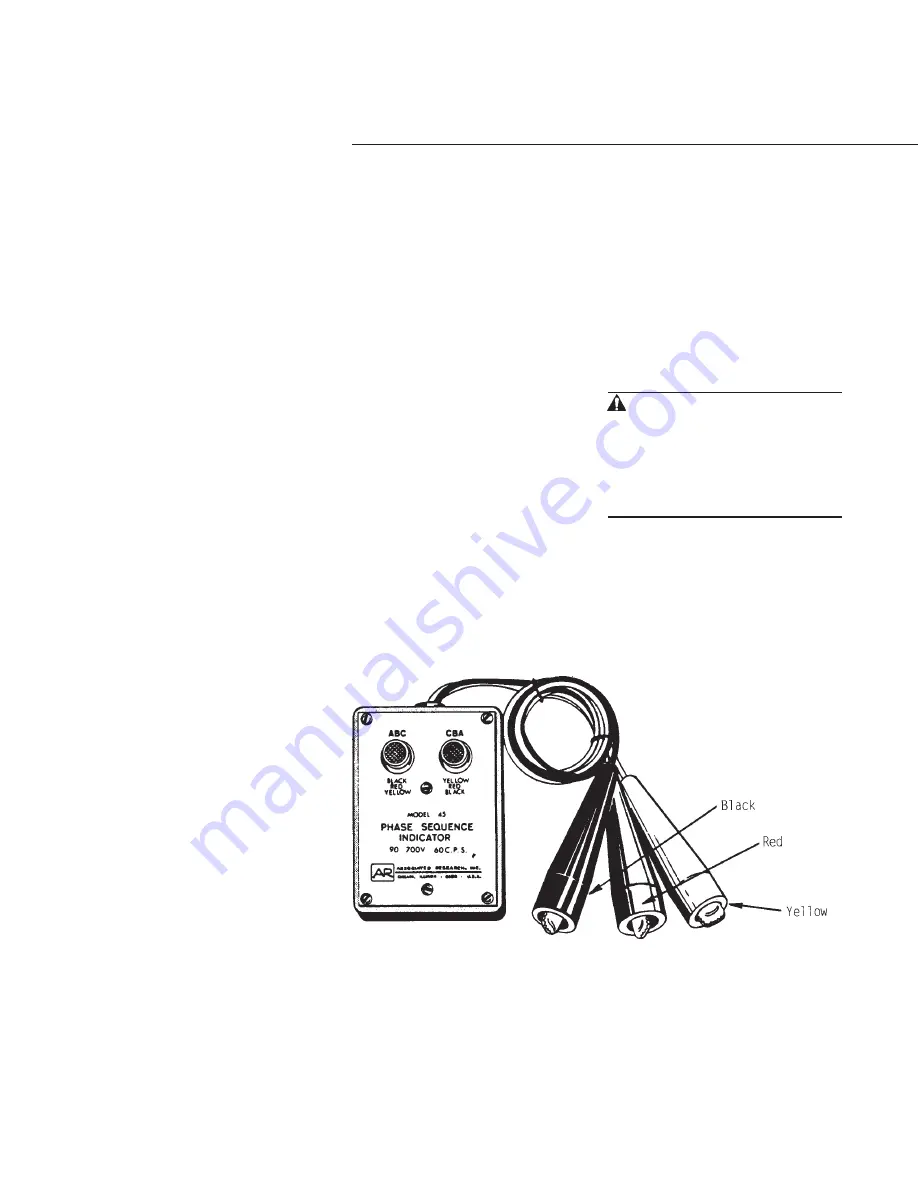
Associated Research Model 45 Phase
Sequence Indicator shown in Figure 55,
and follow this procedure.
WARNING
IT IS IMPERATIVE THAT L1-L2-L3
IN THE STARTER BE
CONNECTED IN THE A-B-C
PHASE SEQUENCE TO PREVENT
EQUIPMENT DAMAGE DUE TO
REVERSE ROTATION.
Figure 55
Associated Research Model 45
Phase Sequence Indicator
Summary of Contents for RTAA-130
Page 2: ... American Standard Inc 1991 ...
Page 8: ...8 RTAA IOM 3 ...
Page 24: ...24 RTAA IOM 3 ...
Page 50: ...50 RTAA IOM 3 Figure 30 Refrigerant Circuit Identification ...
Page 52: ...52 RTAA IOM 3 Figure 31 Remote Evaporator Piping Example ...
Page 59: ...59 RTAA IOM 3 Continued from Previous Page See Notes on Next Page ...
Page 63: ...63 RTAA IOM 3 Continued from Previous Page See Notes on Page 61 ...
Page 65: ...65 RTAA IOM 3 Continued from Previous Page See Notes on Page 61 ...
Page 76: ...76 RTAA IOM 3 ...
Page 92: ...92 RTAA IOM 3 Figure 51 Operator Interface Controls ...
Page 120: ...120 RTAA IOM 3 ...
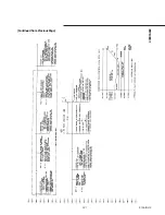
Page 127: ...127 RTAA IOM 3 Continued from Previous Page 2307 1566C ...
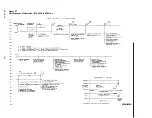
Page 128: ...128 RTAA IOM 3 Figure 57 Unit Sequence of Operation RTAA 130 to 200 Tons 2306 9122A ...
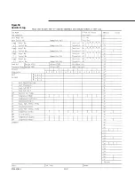
Page 132: ...132 RTAA IOM 3 Figure 58 Operator s Log ...
Page 138: ...138 RTAA IOM 3 ...

