130
RTAA-IOM-3
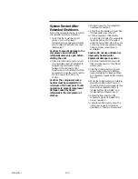
System Restart After
Extended Shutdown.
Follow the procedures below to restart
the unit after extended shutdown:
1. Verify that the liquid line service
valves, oil line, compressor
discharge service valves and suction
service valves (if installed) are open
(backseated).
Caution: To prevent damage to the
compressor, be sure that all
refrigerant valves are open before
starting the unit.
2. Close the main disconnect and unit
mounted disconnect (if installed) to
energize the compressor sump
heaters. If the optional control
transformer is not installed, it will be
necessary to close the disconnect for
115 VAC power to 1TB3-1 and
1TB3-2.
Caution: The compressor sump
heaters must be energized for a
minimum of 24 hours prior to unit
operation, to prevent compressor
damage caused by liquid
refrigerant in the compressor at
start-up.
3. Maintain power to the evaporator
heat tape connections.
4. Check the oil separator oil level. See
“Oil Separator Level Check”.
5. Fill the evaporator chilled water
circuit. Refer to Table I for evaporator
liquid capacities. Vent the system
while it is being filled. Open the vent
on the top of the evaporator during
filling and close when filling is
completed.
Caution: Do not use untreated or
improperly treated water.
Equipment damage may occur.
6. Close the fused-disconnect switch
that provides power to the chilled
water pump.
7. Start the chilled water pump and,
while chilled water is circulating,
inspect all piping for leakage. Make
any necessary repairs before starting
the unit.
8. While the chilled water is circulating,
adjust the chilled water flow and
check the chilled water pressure drop
through the evaporator. Refer to
“Water System Flow Rates” and
“Water System Pressure Drop”.
9. Adjust the flow switch on the
evaporator piping (if installed) for
proper operation.
10. Stop the chilled water pump. The
unit is now ready for start-up as
described in “Start-Up Procedures”.
Summary of Contents for RTAA-130
Page 2: ... American Standard Inc 1991 ...
Page 8: ...8 RTAA IOM 3 ...
Page 24: ...24 RTAA IOM 3 ...
Page 50: ...50 RTAA IOM 3 Figure 30 Refrigerant Circuit Identification ...
Page 52: ...52 RTAA IOM 3 Figure 31 Remote Evaporator Piping Example ...
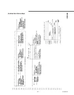
Page 59: ...59 RTAA IOM 3 Continued from Previous Page See Notes on Next Page ...
Page 63: ...63 RTAA IOM 3 Continued from Previous Page See Notes on Page 61 ...
Page 65: ...65 RTAA IOM 3 Continued from Previous Page See Notes on Page 61 ...
Page 76: ...76 RTAA IOM 3 ...
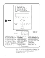
Page 92: ...92 RTAA IOM 3 Figure 51 Operator Interface Controls ...
Page 120: ...120 RTAA IOM 3 ...
Page 127: ...127 RTAA IOM 3 Continued from Previous Page 2307 1566C ...
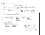
Page 128: ...128 RTAA IOM 3 Figure 57 Unit Sequence of Operation RTAA 130 to 200 Tons 2306 9122A ...
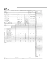
Page 132: ...132 RTAA IOM 3 Figure 58 Operator s Log ...
Page 138: ...138 RTAA IOM 3 ...

