133
RTAA-IOM-3
Refrigerant Emission
Control
Evidence from environmental scientists
indicates that the ozone in our upper
atmosphere is being reduced, due to
the release of CFC fully halogenated
compounds.
The Trane Company encourages every
effort to eliminate, if possible, or
vigorously reduce the emission of CFC,
HCFC and HFC refrigerants into the
atmosphere that result from
installation, operation, routine
maintenance, or major services on this
equipment. Always act in a responsible
manner to conserve refrigerants for
continued use, even when acceptable
alternatives are available.
Conservation and emission reduction
can be accomplished by following
recommended Trane operation,
maintenance and service procedures,
with specific attention to the following:
1. Refrigerant used in any type of air
conditioning or refrigerating
equipment should be recovered for
reuse, recovered and/or recycled for
reuse, reprocessed (reclaimed), or
properly destroyed, whenever it is
removed from equipment. Never
release refrigerant into the
atmosphere.
2. Always determine possible recycle or
reclaim requirements of the
recovered refrigerant before
beginning recovery by any method.
Questions about recovered
refrigerants and acceptable
refrigerant quality standards are
addressed in ARI Standard 700.
3. Use approved containment vessels
and safety standards. Comply with
all applicable transportation
standards when shipping refrigerant
containers.
4. To minimize emissions while
recovering refrigerant, use recycling
equipment. Always attempt to use
methods which will pull the lowest
possible vacuum while recovering
and condensing refrigerant into
containment.
5. When leak checking with trace
refrigerant and nitrogen, use HCFC-
22 (R-22), rather than CFC-12 (R-12)
or any other fully halogenated
refrigerants. Be aware of any new
leak test methods which eliminate
refrigerant as a trace gas.
6. When cleaning system components
or parts, avoid using CFC-11 (R-11) or
CFC-113 (R-113). Refrigeration
system
cleanup methods which use filters and
dryers are preferred. Do not use
solvents which have ozone depletion
factors. Properly dispose of used
materials.
7. Take extra care to properly maintain
all service equipment that directly
supports refrigeration service work,
such as gauges, hoses, vacuum
pumps and recycling equipment.
8. Stay aware of unit enhancements,
conversion refrigerants, compatible
parts and manufacturer’s
recommendations which will reduce
refrigerant emissions and increase
equipment operating efficiencies.
Follow manufacturer’s specific
guidelines for conversion of existing
systems.
9. In order to assist in reducing power
generation emissions, always
attempt to improve equipment
performance with improved
maintenance and operations that will
help conserve energy resources.
Weekly Maintenance
After the unit has been operating for
approximately 30 minutes and the
system has stabilized, check the
operating conditions and complete the
procedures below:
[ ] Check the evaporator refrigerant
pressure (23) and the condenser
refrigerant pressure (25) in Menu 2
on the UCM. The pressures are
referenced to sea level (114.6960
psia).
[ ] Check the liquid line sight glasses.
The refrigerant flow past the sight
glasses should be clear. Bubbles in
the refrigerant indicate either low
refrigerant charge or excessive
pressure drop in the liquid line. A
restriction in the line can sometimes
be identified by a noticeable
temperature differential between
the two sides of the restriction. Frost
may often form on the line at this
point. Proper refrigerant charges are
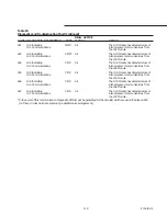
shown on Table 1.
Caution: A clear sight glass alone
does not mean that the system
properly charged. Also check
system superheat, subcooling, and
unit operating pressures.
Summary of Contents for RTAA-130
Page 2: ... American Standard Inc 1991 ...
Page 8: ...8 RTAA IOM 3 ...
Page 24: ...24 RTAA IOM 3 ...
Page 50: ...50 RTAA IOM 3 Figure 30 Refrigerant Circuit Identification ...
Page 52: ...52 RTAA IOM 3 Figure 31 Remote Evaporator Piping Example ...
Page 59: ...59 RTAA IOM 3 Continued from Previous Page See Notes on Next Page ...
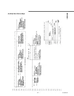
Page 63: ...63 RTAA IOM 3 Continued from Previous Page See Notes on Page 61 ...
Page 65: ...65 RTAA IOM 3 Continued from Previous Page See Notes on Page 61 ...
Page 76: ...76 RTAA IOM 3 ...
Page 92: ...92 RTAA IOM 3 Figure 51 Operator Interface Controls ...
Page 120: ...120 RTAA IOM 3 ...
Page 127: ...127 RTAA IOM 3 Continued from Previous Page 2307 1566C ...
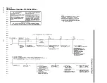
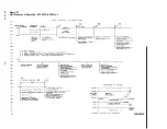
Page 128: ...128 RTAA IOM 3 Figure 57 Unit Sequence of Operation RTAA 130 to 200 Tons 2306 9122A ...
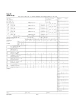
Page 132: ...132 RTAA IOM 3 Figure 58 Operator s Log ...
Page 138: ...138 RTAA IOM 3 ...

