86
RTAA-IOM-3
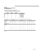
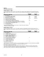
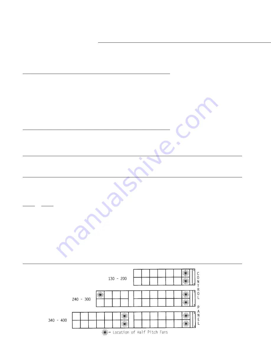
Figure 46
Fan Configurations - RTAA 130-400 Tons - 0 F Minimum Ambient
The 0 F AMBIENT OPTION will have Half Airflow (Half Pitch Blade) Fan.
# Of Fans
# Of Fans
UCM Outputs
Tons
Circuit #1
Circuit #2
Per Circuit
Fan Steps/Circuit
130
5*
6*
4
9 & 10 respectively
140
5*
6*
4
9 & 10 respectively
155
6*
6*
4
10 & 10 respectively
170
7*
6*
4
11 & 10 respectively
185
7*
7*
4
11 & 11 respectively
200
7*
7*
4
11 & 11 respectively
215
7*
7*
4
11 & 11 respectively
240
10**
7*
4
9 & 11 respectively
270
12**
7*
4
10 & 11 respectively
300
14**
7*
4
11 & 11 respectively
340
10**
14**
4
9 & 11 respectively
370
12**
14**
4
10 & 11 respectively
400
14**
14**
4
11 & 11 respectively
*The first fan on each single compressor circuit is a Half Airflow (Half Pitch Blade) Fan.
**The first two fans on each dual compressor circuit are Half Airflow (Half Pitch Blade) Fans.
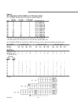
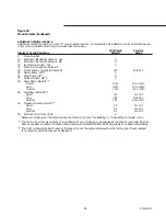
For 0 F AMBIENT OPTION air-cooled (RTAA) Chillers, the mapping of UCM outputs to fan staging shall be as follows:
Fan Contactor
5 & 10 Fan Circuit
6 & 12 Fan Circuit
7 & 14 Fan Circuit
Circuit #1
K9
K10
K11
K12
K9
K10
K11
K12
K9
K10
K11
K12
Circuit #2
K13
K14
K15
K16
K13
K14
K15
K16
K13
K14
K15
K16
Number of
Fans/Contactor
Single Comp. Ckt.
1*
1
1
2
1*
1
2
2
1*
1
2
3
Dual Comp. Ckt. 2*
2
2
4
2*
2
4
4
2*
2*
2
4
6
* = Half AirFlow Fan
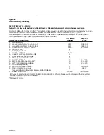
Fan Steps
Single
Dual
Compr
Compr
Ckt
Ckt
0.0
0.0
–
–
–
–
–
–
–
–
–
–
–
–
0.5
1
x
–
–
–
x
–
–
–
x
–
–
–
1
2
–
x
–
–
–
x
–
–
–
x
–
–
1.5
3
x
x
–
–
x
x
–
–
x
x
–
–
2
4
–
x
x
–
–
–
x
–
–
–
x
–
2.5
5
x
x
x
–
x
–
x
–
x
–
x
–
3
6
–
x
–
x
–
x
x
–
–
–
–
x
3.5
7
x
x
–
x
x
x
x
–
x
–
–
x
4
8
–
x
x
x
–
–
x
x
–
x
–
x
4.5
9
x
x
x
x
x
–
x
x
x
x
–
x
5.5
11
–
–
–
–
x
x
x
x
x
–
x
x
6.5
13
–
–
–
–
–
–
–
–
x
x
x
x
X = ON
Summary of Contents for RTAA-130
Page 2: ... American Standard Inc 1991 ...
Page 8: ...8 RTAA IOM 3 ...
Page 24: ...24 RTAA IOM 3 ...
Page 50: ...50 RTAA IOM 3 Figure 30 Refrigerant Circuit Identification ...
Page 52: ...52 RTAA IOM 3 Figure 31 Remote Evaporator Piping Example ...
Page 59: ...59 RTAA IOM 3 Continued from Previous Page See Notes on Next Page ...
Page 63: ...63 RTAA IOM 3 Continued from Previous Page See Notes on Page 61 ...
Page 65: ...65 RTAA IOM 3 Continued from Previous Page See Notes on Page 61 ...
Page 76: ...76 RTAA IOM 3 ...
Page 92: ...92 RTAA IOM 3 Figure 51 Operator Interface Controls ...
Page 120: ...120 RTAA IOM 3 ...
Page 127: ...127 RTAA IOM 3 Continued from Previous Page 2307 1566C ...
Page 128: ...128 RTAA IOM 3 Figure 57 Unit Sequence of Operation RTAA 130 to 200 Tons 2306 9122A ...
Page 132: ...132 RTAA IOM 3 Figure 58 Operator s Log ...
Page 138: ...138 RTAA IOM 3 ...

