99
RTAA-IOM-3
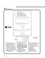
Chiller Switch
The chiller switch has three positions:
Top Position
AUTO REMOTE
Middle Position
AUTO LOCAL
Bottom Position
STOP/RESET
With the switch in the AUTO REMOTE
position, the chiller will operate
normally using remote setpoints. Read
and write remote communications may
be performed. Any call for cooling
based on Leaving Water Temperature
(LWT) and the remote (e.g. Tracer)
setpoints, will start the unit. The active
chilled water setpoint (CWS) can be the
remote CWS, a reset remote setpoint
based on return, zone, or outdoor
temperature reset, or a 4-20 mA/0-10
VDC external CWS. The active Current
Limit Setpoint (CLS) can be the Remote
CLS or a 4-20 mA/0-10 VDC External
CLS. If remote communication is lost,
the UCM will revert to the Front Panel
(or local) chiller settings.
When the chiller switch is in the AUTO
LOCAL position, the chiller will operate
normally using Front Panel (or local)
setpoints. Read and write remote
communications may be performed,
but remote setpoints cannot be used
for control. The unit will run when there
is a call for cooling based on the LWT
and the Front Panel or local setpoints.
The active CWS can be the local
setpoint, a reset setpoint based on
return, zone, or outdoor temperature
reset, or a 4-20 mA/0-10 VDC external
CWS. The active Current Limit Setpoint
can be the local setpoint or a 4-20 mA/
0-10 VDC External CLS. Remote (e.g.
Tracer) setpoints communicated over
the serial communications link will be
ignored, but remote devices can still
read all unit control data.
In the STOP/RESET position, the UCM
is powered but operation of the unit is
prevented. All outputs are de-energized
and the chiller is stopped. The alarm
relay output may be energized if an
alarm condition exists.
If any of the chillers are running when
the chiller is put into the STOP/RESET
position, the chiller will go into the Run:
Unload mode for at least 20 seconds
before shutting down the compressors.
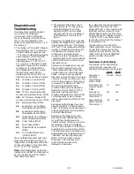
Although not a “position” on the chiller
switch, it can be used to perform the
function of manually resetting all
latching diagnostics and clearing all
historic diagnostics. Latching
diagnostics can be reset by manually
toggling the chiller switch from the
STOP/RESET position to either AUTO
position.
Historic diagnostics (“C” menu item)
can be cleared by depressing the
“Display Down” key while manually
toggling the chiller switch from the
STOP/RESET position to either AUTO
position (no compressor operating).
Moving the chiller switch from the
STOP/RESET position to either AUTO
position will reset the controls, with
one exception. If the chiller operating
status is Run:Unload, this sequence will
go to completion before the reset is
executed. During the completion of the
Run:Unload, the reset is “queued up”
and operated on only after completion
of the Run:Unload. After reset is
completed, the digital display will
return to “A” Operating Code.
Summary of Contents for RTAA-130
Page 2: ... American Standard Inc 1991 ...
Page 8: ...8 RTAA IOM 3 ...
Page 24: ...24 RTAA IOM 3 ...
Page 50: ...50 RTAA IOM 3 Figure 30 Refrigerant Circuit Identification ...
Page 52: ...52 RTAA IOM 3 Figure 31 Remote Evaporator Piping Example ...
Page 59: ...59 RTAA IOM 3 Continued from Previous Page See Notes on Next Page ...
Page 63: ...63 RTAA IOM 3 Continued from Previous Page See Notes on Page 61 ...
Page 65: ...65 RTAA IOM 3 Continued from Previous Page See Notes on Page 61 ...
Page 76: ...76 RTAA IOM 3 ...
Page 92: ...92 RTAA IOM 3 Figure 51 Operator Interface Controls ...
Page 120: ...120 RTAA IOM 3 ...
Page 127: ...127 RTAA IOM 3 Continued from Previous Page 2307 1566C ...
Page 128: ...128 RTAA IOM 3 Figure 57 Unit Sequence of Operation RTAA 130 to 200 Tons 2306 9122A ...
Page 132: ...132 RTAA IOM 3 Figure 58 Operator s Log ...
Page 138: ...138 RTAA IOM 3 ...

