RLC-SVD05A-EN
27
Current Transformers
Where:
I0x = the phase with the largest difference from Iave.
5
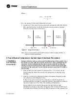
Current Limit. The current limit range for each compressor is 60-120% RLA for
RTAC and 40-100% RLA for RTHD. The figure below provides a graphical
illustration of the current limit control.
Figure 13
Current Limit Control
.O
,IMIT
,IMIT
,OADING
(OLD
&ORCED
5NLOAD
$IAGNOSTIC4
RIP
#,3
#,3
#,3
#,3
Note: The current transformers are NOT polarity or directionally sensitive in
RTAC and RTHD applications
CT and Starter Compressor Current Input Checkout Procedure
WARNING
Live Electrical
Components!
During installation, testing, servicing and troubleshooting of this product, it may
be necessary to work with live electrical components. Have a qualified licensed
electrician or other individual who has been properly trained in handling live
electrical components perform these tasks. Failure to follow all electrical safety
precautions when exposed to live electrical components could result in death or
serious injury.
1
Check incoming 3-phase power for voltage /- 10% of nominal per
Chiller nameplate. Verify that unit size and voltage are set correctly using
TechView.
2
Check for all of the active diagnostic codes or the historic diagnostic codes
using TechView under Diagnostic View.
If there is any question as to which compressor or current transformer is
causing a problem, or simply to verify and “witness” the problem, an attempt
should be made to start the chiller after resetting all diagnostics.
It is possible to “force” specific compressors to be the first or next
compressor to stage on, using the “Compressor Test” feature of Tech View in
Compressor Service View. The Leaving Water Temperature must, however, be
Iave =
I01+I02+I03
3


