RTWB-SVN01B-E4
21
Installation Electrical
Interconnecting wiring
IIM
MP
PO
OR
RT
TA
AN
NT
T
Do not turn the chiller on or off
using the chilled-water interlocks.
When making field connections,
refer to the appropriate field layout,
wiring schematics, and control
diagrams that ship with the unit.
Chilled-water pump control
C
CA
AU
UT
TIIO
ON
N
The chilled-water pump must
operate for a minimum of one
minute after the UCM receives a
command, through the external
Auto/Stop input, to shut down the
chilled-water system.
On the RTWB units, the controller
will initiate the “Run:Unload“ mode
to terminate a cycle from any of the
following:
- Stop key pressed
- Loss of load
- External Auto/Stop input opened
The “Run:Unload“ operating mode
commands the compressor to
completely unload, which takes
about ½ minute. This will allow the
compressors to be totally unloaded
for the next start-up. If only the
proof-of-chilled-water-flow interlock
is used, the chiller will shut down
with an immediate (non-friendly)
shutdown and initiate an automatic
reset diagnostic.
1. External Auto/Stop (terminals A1
TB3-3 and -4)
This input is supplied by the field.
A contact closure will start the
chiller water pump and chiller, via
the UCM pump control contacts.
Opening the contact will put the
operating compressors into
“Run:Unload“ mode and initiate a
timing period (1 to 30 minutes,
adjustable through the Clear
Language Display). This will delay
termination of the chilled-water
pump operation via the UCM
pump control contacts. Examples
of the input terminals 1UTB3-3
and -4 would be a time clock,
ambient thermostat, building
automation system.
2. UCM Pump Control Contacts
(Terminals A1 TB4-8 and -9)
This output is a set of contacts
that will close, starting the chilled-
water pump when the external
Auto/Stop contacts are closed.
When the contacts are opened, 1
to 30 minutes later (adjustable
through the Clear Language
Display), the UCM pump control
contacts open.
3. Proof-of-Chilled-Water-Flow
Interlock (Terminals A1 TB3-1 and
-2) This terminal must be field-
installed. Contact closure
between the terminals indicates
proof of chilled-water flow.
Examples of this are a pump
starter auxiliary contact, flow
switch, differential pressure
switch, or a contact from a
building automation system.
Opening of this contact will
immediately shut down the chiller
and initiate an automatic reset
diagnostic, indicating loss of
chilled-water flow
4. Condenser-Water Pump
For the condenser-water pump
interlock on the RTWB units,
connect leads from terminals 6X3
to 6X6 and the water pump
control. The circuit is 110 V (ac)and
the load is not to exceed 1150 VA
inrush, 115 VA sealed.
This will interlock the condenser-
water pump operation with the
unit operation. This insures that
the condenser-water pump is
operating before the
compressor(s) is started.
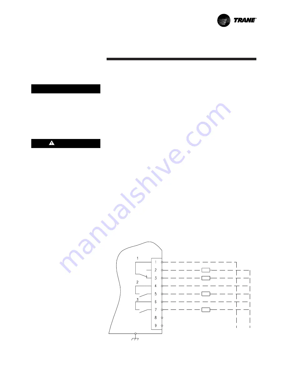
5. Alarm/Running/Maximum
Capacity Outputs
Terminals 1 to 7 on terminal strip
TB4 of the A1 board provide a
variety of contact outputs on the
RTWB. These are dependent on
the setting of Programmable
Relay Setup (Service Setting
Menu) and its relationship to
diagnostics, compressors
operating, and the system
operating at full capacity.
As shown in Figure 13, there are
three relays.
Figure 13 – Alarm / Running / Maximum capacity relay output for the RTWB unit.


