Installation
CVRF-SVN005C-EN
19
1. Installing Symbio™ stepper actuator.
a. Determine the inlet guide vane stroke by manually
closing and opening the vanes and accurately
measuring the length of travel.
b. Record this value as it will be used when performing the
post conversion checkout.
2. Remove the existing IGV actuator and existing conduit and
wire.
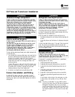
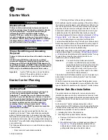
3. Install the new IGV actuator on the chiller.
a. Use the connecting hardware retained when the old
actuator was removed.
b. Use the existing actuator mounting plate, piston yoke
and mounting hardware to install the new electric
actuator.
The motor can be rotated 180 degrees to accommodate
existing hardware. The actuator rod may be connected to
the mounting plate at the compressor housing or to the
vane linkage.
NOTICE
Equipment Damage!
Failure to ensure that the 0 degree vane position
corresponds with the actuator fully closed when
mounting the actuator could result in severe damage to
the machine.
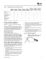
Figure 11. Installed stepper IGV actuator
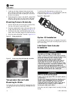
4. The IGV ships in a mid-position. The first time the IGV is
powered up, it will drive closed. This may mean travel as
much as 1 inch. Disconnect the IGV actuator from the IGV
linkage until fully retracted.
Running the IPC Bus
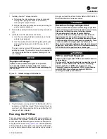
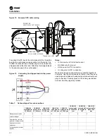
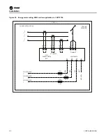
There are several ways to string the IPC communication bus
on the chiller. The Symbio™ retrofit kit includes a general wire
kit that has several different types of wires. An example of a
wiring layout can be seen in
. Each application
will vary depending on the options. You may have extra cables,
or may be short needed cables. Extra cables can be ordered
through your local Trane Parts Center. Refer to PART-SVB16*-
EN for identification of individual cables.
WARNING
Hazardous Voltage w/Capacitors!
Failure to disconnect power and discharge capacitors
before servicing could result in death or serious injury.
Disconnect all electric power, including remote
disconnects and discharge all motor start/run
capacitors before servicing. Follow proper lockout/
tagout procedures to ensure the power cannot be
inadvertently energized. For variable frequency drives
or other energy storing components provided by Trane
or others, refer to the appropriate manufacturer’s
literature for allowable waiting periods for discharge of
capacitors. Verify with a CAT III or IV voltmeter rated per
NFPA 70E that all capacitors have discharged.
WARNING
PPE for Arc/Flash Required!
Failure to wear appropriate PPE could result in death or
serious injury.
On this unit, if the handle shield is cracked the circuit
breaker could arc/flash when reset. To avoid being
injured, technicians MUST put on all necessary
Personal Protective Equipment (PPE), in accordance
with NFPA70E for arc/flash protection, PRIOR to
entering the starter panel cabinet.


