Installation
CVRF-SVN005C-EN
21
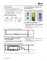
Purge Control Installation
Important:
Be sure to retain all existing purge safety
controls!
The purge power line connections for the power to the unit
should be wired per the purge wiring diagram. In general the
115 Vac power for the purge originates from the unit control
panel. In the new control panel a circuit breaker 1Q2 is
provided to power the purge. A neutral connection can be
found on the 1X1 terminal strip.
PRGC Purifier Purge
The PRGC Purifier™ purge uses UCP2-based
communications and does not communicate with Tracer®
AdaptiView™ controls. To convert the purge to a standalone
purge, order KIT02586 from a Trane Parts Center and install it,
making sure to install a jumper between terminals J1-5 and J1-
6 on the 3UI module when doing the conversion. A PRGC
requires a compressor running signal connected to J26, 1 and
2 on 3U1 in the purge to operate in the auto or adaptive modes.
Use the Compressor Running contact closure from the quad
relay LLID - 1A8, connected to 115 Vac purge source.
PRGD, PRGG and PRGF EarthWise Purge
If a stand-alone EarthWise purge (CH530 control) exists on the
chiller, it will need some hardware changes to work with the
Symbio™ retrofit controls. If the purge is a new installation with
the Symbio™, then skip to
.
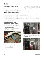
1. The compressor running LLID (3A6) will not be needed,
disconnect and remove.
2. The condenser saturated refrigerant temperature LLID
(purge liquid temperature) will not be needed, disconnect
and remove.
3. The existing 120-27 Vac transformer and DC power supply
in the purge is undersized and should be removed. The
purge control will be powered by the Symbio™ panel
power supply.
4. Remove and save purge power supply LLID.
5. Remove IPC bus cable from power supply LLID. (Ensure
remaining LLIDs are still connected to IPC bus).
6. It is optional to remove and discard the wires (303A, 304A,
and 318A) from control power transformer to this power
supply LLID (3A5).
7. Disconnect the cable from the DynaView to the power
supply LLID.
8. Remove the tilt bracket from the purge base. DynaView
can remain attached to the tilt bracket panel.
9. Connect the IPC bus from the control panel to the IPC bus
for the purge using an IPC bus cable.
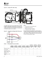
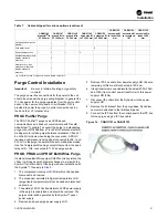
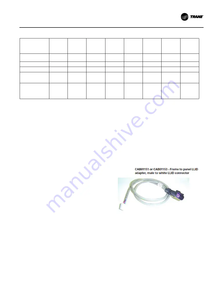
Figure 14. CABO1151 or CABO1153
Hot gas bypass—pulse
actuator
1
1
Cold water reset
1
8
Enhanced protection
1
2
1
3
Chilled/tower water flow
display, standard
accuracy
2
Heat recovery / aux
condenser water flow
display, standard
accuracy
1
(a) The letters M and F represent male and female connectors.
Table 7.
Cables shipped for various options (continued)
CAB01146
branch M
(a)
to
2F 500 mm
CAB01147
branch M to
2F 1000 mm
CAB01148
branch M to
3F 500 mm
CAB01149
extension M
to F 1000 mm
CAB01150
extension M
to F 2000 mm
CAB01152
extension M
to leads 1000
mm
CAB01154
extension M
to receptacle
1M
CAB01155
extension F to
leads 1000
mm


