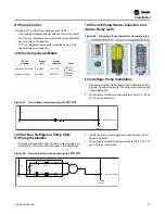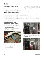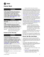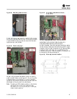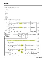
Figure 29. Cast – ½ inch NPTI port
Installation
26
CVRF-SVN005C-EN
Preparation of Wells
Install the provided well using bushings as needed.
Water Box Valve Mounting
Mount transducers on the entering and leaving side water box
locations with the strainer horizontal, the strainer clean out port
pointing down and the transducer facing upwards and connect
to unit control buss. After system is filled, loosen the transducer
in its threaded fitting. Then crack the isolation valve until water
starts dripping from threads. Close the valve and re-tighten the
transducer, and then reopen the valve for use.
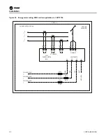
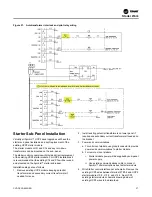
Figure 30. Standard accuracy flow meter wiring, ref.
50712746
High Accuracy, Customer Provided
Meter Option
The high accuracy customer provided meter option provides
an analog input/output LLID to monitor a customer provided
high accuracy meter 0-10 Vdc or 4 – 20 mA outputs.
(Rosemont, etc.) This option allows monitoring of condenser,
evaporator flow and auxiliary heat exchangers.
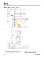
Install needed DAIO LLID(s) (BRD04873) in CVRF control
panel:
1. LLID (1A21) is needed for EVAP and COND water flow.
Connect flow meter wires to 1A21-J2-1 and 1A21-J2-1 for
EVAP, 1A21-J2-4 and 1A21-J2-5 for COND.
2. LLID (1A28) is need for HR Aux/COND water flow.
Connect flow meter wires 1A28-J2-1 and 1A28-J2-1 for HR
flow or Aux COND.
IPC BUS
LINE 269
-
Pg
+
SIG
4BP4
-
Pg
+
SIG
4BP5
-
Pg
+
SIG
4BP6
-
Pg
+
SIG
4BP7
WATER PRESSURE
EVAP ENTERING
OPTIONAL
TRANSDUCER
WATER PRESSURE
EVAP LEAVING
OPTIONAL
TRANSDUCER
WATER PRESSURE
COND ENTERING
OPTIONAL
TRANSDUCER
WATER PRESSURE
COND LEAVING
OPTIONAL
TRANSDUCER


