Installation
CVRF-SVN005C-EN
29
The meter is connected to Modbus communications and is
self-powered by the unit voltage potential inputs. Review meter
literature for setup and operation details.
Modbus communications is by shielded 14 – 26 AWG cable
from meter to Symbio™ module. Please install 120 OHM
resistors at first and last modules on Modbus daisy chain.
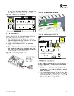
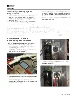
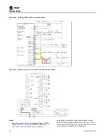
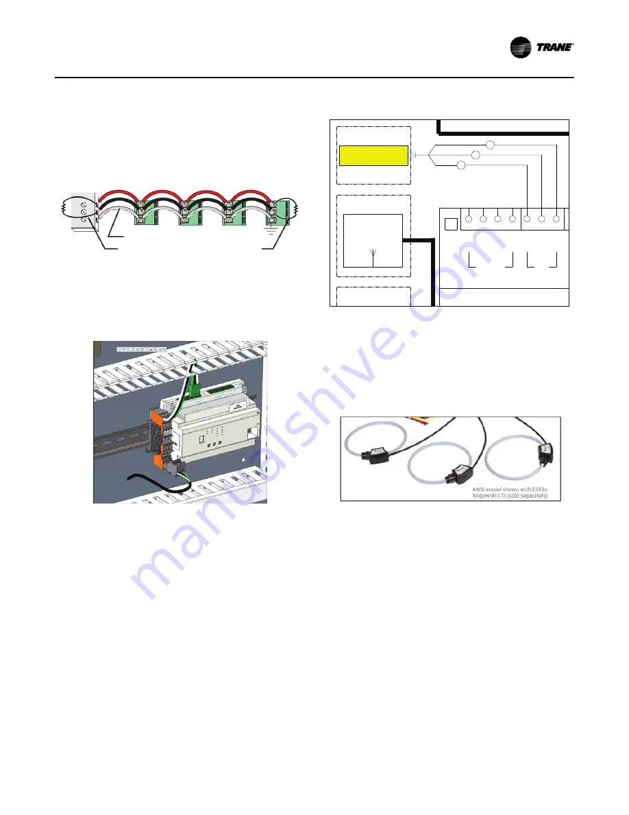
Figure 35. Modbus communication
The communications wiring will be terminated at the Modbus
distribution terminal (1X3) beside Symbio™ 800 using the 3
poles connector which provide in energy meter kits.
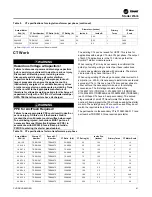
Figure 36. Distribution terminal
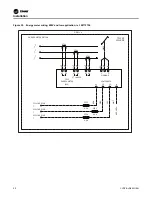
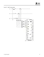
Figure 37. Modbus wiring, ref. 50712738
480 Volts and Lower Installations
POTENTIAL INPUT – Install provided fused inputs to line
voltage per schematic.
CURRENT INPUT – Install provided Rogowski CTs per
schematic.
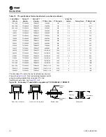
Figure 38. Rogowski CTs
–
S
+
Shielded Wire
120 terminators on the first/last devices of daisy
chain
Ω
-
+
BACKNET
P1
-
+
-
+
MODBUS
P2
G
ENERGY METER
OPTIONAL
LINE 52
IMC
A
1A22 SYMBIO800 UNIT CON
WI-FI
4Y1
ANTENNA
OPTIONAL
WHT
GRN
BLK
OPTIONAL
1X3-1
1X3-2
1X3-3
BLK
BLU
RED


