TRANE
R
Installation
7
Foundation
When selecting and preparing the unit
site, follow these guidelines:
1. Ensure that the site can support the
total weight of the unit. Unit weight
figures only provide total gross
weights and do not include the
additional weight for water in any
coils.
2. Confirm that the foundation of the
mounting platform is large enough
to include the unit dimensions plus
service plus service access.
3. The floor or foundation must be
level for correct coil drainage and
condensate flow.
4. Provide adequate lighting for
maintenance personnel to perform
maintenance duties.
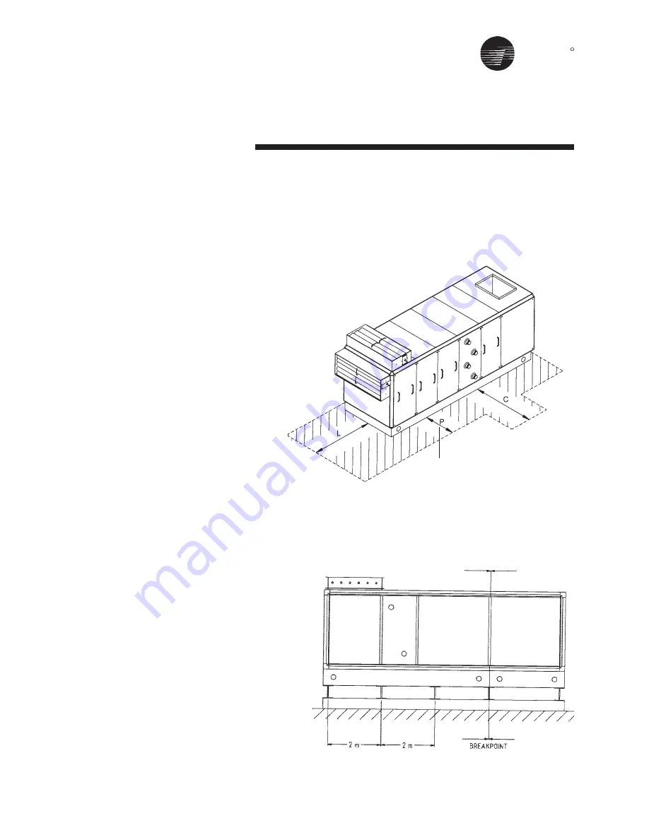
5. When the unit is positioned on site,
there must be sufficient space
around the unit to ensure that correct
operation and effective main-
tenance can be carried out. Figure
6 gives recommended space
allowances.
•
On the designated access side of
the unit, working areas must have
minimum 1 mtr, space (P).
•
Allowance for coil connections,
dimension “C” must be dimension
200mm + unit width.
•
A clear unobstructed area before
and after an air intake or discharge
is required to ensure correct air
movement. The width of the area
must be >= the width of the unit, and
the depth (dimension “L”) must be
>= 0.5 x the overall unit height.
Complete reinforced concrete
foundations are suitable or strip
foundations may also be used (see
Figure 7).
In the case of strip foundations,
concrete or steel supports are
premissible, but support is required
under breakpoints and every 2 m along
the unit base.
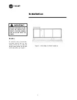
Figure 7 - Air Handling Unit Steels Foundation
Figure 6
P = 1 MTR min
Summary of Contents for TRANE Quantum CLCPEuro
Page 2: ...TRANE R...
Page 6: ...TRANE R 2 CLCPXP Model Nomenclature...
Page 7: ...TRANE R CLCPEURO Model Nomenclature 3...
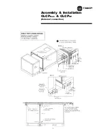
Page 13: ...TRANE R Assembly Installation CLCPEuro CLCPXP External connection 9...
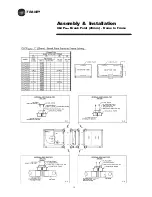
Page 14: ...TRANE R Assembly Installation CLCPEuro Break Point 25mm Frame to Frame 10...
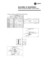
Page 15: ...TRANE R 11 Assembly Installation CLCPEuro Break Point 25mm Panel to Frame...
Page 16: ...TRANE R 12 Assembly Installation CLCPEuro Break Point 2 50mm Frame to Frame...
Page 17: ...TRANE R Assembly Installation CLCPEuro Break Point 2 50mm Panel to Frame 13...
Page 18: ...TRANE R Assembly Installation CLCPEuro Paneling 14...
Page 19: ...TRANE R Assembly Installation CLCP XP Break Point 15...
Page 20: ...TRANE R Assembly Installation CLCP XP Break Point 16...
Page 21: ...TRANE R 17 Assembly Installation CLCP...
Page 22: ...TRANE R Assembly Installation CLCP 18...
Page 36: ...TRANE R Maintenance 32 Figure 18 Belt Tension Measurement...
Page 39: ...TRANE R 35 Trouble Analysis Pulley and Belt...
Page 45: ...TRANE R Appendix B HDT Unit Weight CLCPXP 41...
Page 46: ...TRANE R Appendix B HDT Unit Weight CLCPXP 42...
Page 47: ...TRANE R Appendix B HDT Unit Weight CLCPXP 43...
Page 48: ...TRANE R Appendix B VDT Unit Weight CLCPXP 44...
Page 53: ...TRANE R Appendix D Filter and Quantity 49 Filter Dimension and Arrangement Final Filter HEPA...
Page 57: ...TRANE R Typical Wiring Diagram Starter Star Delta 380 420V 3Phase 4Wires ELCB Standard 53...
Page 58: ...TRANE R 54 Typical Wiring Diagram Starter Dol 380 420V 3Phase 4Wires ELCB Standard...
Page 59: ...TRANE R 55 Typical Wiring Diagram Starter Dol 380 420V 3Phase 4Wires Standard...
Page 62: ...TRANE R 58 Typical Wiring Diagram Starter Dol 380 420V 3Phase 4Wires Standard...
Page 65: ...TRANE R 61 Typical Wiring Diagram Starter Star Delta 380 420V 3Phase 4Wires Standard...
Page 68: ...TRANE R 64...
Page 70: ...TRANE R 66...
Page 71: ...TRANE R...


