TRANE
R
Notice
World enviromental scientists have
concluded, based on the best currently
available evidence, that ozone in our
upper atmosphere is being reduced
due to the release of CFC fully
halogenated compounds.
The Trane Company urges that all
HVAC servicers working on Trane
equipment, or any manufacturer’s
products, make very effort to eliminate,
if possible, or vigorously reduce the
emission of CFC, HCFC and HFC
refrigerants to the atmosphere
resulting from installation, operation,
routine maintenance, or major service
on this equipment. Always act in a
responsible manner to conserve
refrigerants for continued use even
when acceptable alternatives are
available.
Refrigerant used in any type of air-
conditioning or refrigerating equip-
ment should be recovered for reuse,
recovered and / or recycled for reuse,
reprocessed (reclaimed), or properly
destroyed, whenever it is removed from
equipment. Never release to the
atmosphere!
Safety Considerations
The equipment covered by this manual
is designed for safe and reliable
operation when installed and operated
within its design specifcation limits. To
avoid personal injury or damage to
equipment or property while installing
or operating this equipment, it is
essential that qualified, experienced
personnel perform these functions
using good judgement and safe
pratices.
See the following cautionary
statement.
Warning and Cautions
Notice that WARNING and CAUTION
appear at appropriate intervals
throughout this manual.
WARNING indicates a potentially
hazardous situation that could result
in personal injury or death.
CAUTIONs are designed to alert you
to conditions that could result in minor
personal injury or equipment damage.
i
WARNING
!
CAUTION
!
Summary of Contents for TRANE Quantum CLCPEuro
Page 2: ...TRANE R...
Page 6: ...TRANE R 2 CLCPXP Model Nomenclature...
Page 7: ...TRANE R CLCPEURO Model Nomenclature 3...
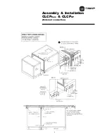
Page 13: ...TRANE R Assembly Installation CLCPEuro CLCPXP External connection 9...
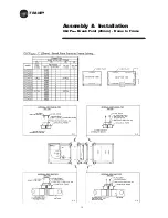
Page 14: ...TRANE R Assembly Installation CLCPEuro Break Point 25mm Frame to Frame 10...
Page 15: ...TRANE R 11 Assembly Installation CLCPEuro Break Point 25mm Panel to Frame...
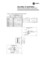
Page 16: ...TRANE R 12 Assembly Installation CLCPEuro Break Point 2 50mm Frame to Frame...
Page 17: ...TRANE R Assembly Installation CLCPEuro Break Point 2 50mm Panel to Frame 13...
Page 18: ...TRANE R Assembly Installation CLCPEuro Paneling 14...
Page 19: ...TRANE R Assembly Installation CLCP XP Break Point 15...
Page 20: ...TRANE R Assembly Installation CLCP XP Break Point 16...
Page 21: ...TRANE R 17 Assembly Installation CLCP...
Page 22: ...TRANE R Assembly Installation CLCP 18...
Page 36: ...TRANE R Maintenance 32 Figure 18 Belt Tension Measurement...
Page 39: ...TRANE R 35 Trouble Analysis Pulley and Belt...
Page 45: ...TRANE R Appendix B HDT Unit Weight CLCPXP 41...
Page 46: ...TRANE R Appendix B HDT Unit Weight CLCPXP 42...
Page 47: ...TRANE R Appendix B HDT Unit Weight CLCPXP 43...
Page 48: ...TRANE R Appendix B VDT Unit Weight CLCPXP 44...
Page 53: ...TRANE R Appendix D Filter and Quantity 49 Filter Dimension and Arrangement Final Filter HEPA...
Page 57: ...TRANE R Typical Wiring Diagram Starter Star Delta 380 420V 3Phase 4Wires ELCB Standard 53...
Page 58: ...TRANE R 54 Typical Wiring Diagram Starter Dol 380 420V 3Phase 4Wires ELCB Standard...
Page 59: ...TRANE R 55 Typical Wiring Diagram Starter Dol 380 420V 3Phase 4Wires Standard...
Page 62: ...TRANE R 58 Typical Wiring Diagram Starter Dol 380 420V 3Phase 4Wires Standard...
Page 65: ...TRANE R 61 Typical Wiring Diagram Starter Star Delta 380 420V 3Phase 4Wires Standard...
Page 68: ...TRANE R 64...
Page 70: ...TRANE R 66...
Page 71: ...TRANE R...


