TRANE
R
and the belts will break or turn over
shortly after installation.
•
Take up sleck until belts fit snugly.
6. Check pulley alignment.
•
Place a straight edge across
pulleys faces to correct alignment.
•
Check parallel position of shafts
and correct alignment or grooves.
•
Note: Mount pulleys as close to
bearing as possible.
31
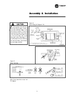
Figure 16
Sheave Alignment
Fan Belt Tension
Note: Fan belt tension should be
checked at least twice during the first
day of operation, since there is a rapid
decrease in tension until belts are run
in.
Proper belt tensioning is required to
ensure maximum bearing and drive
component life and is based on fan
brake horsepower requirement.
Belt Tension Measurement
Check the belt tension as follows:
Measure the span length mm of the
drive. With a belt tensioner at the
center of the span. apply a force K
(perpendicular to the span) large
enough to deflect the belt 15mm per 1
meter of span. Refer to figure 17.
The deflection force for the belt should
be within the minimum and maximum
force shown in the Table 3. When the
tension drops to the minimum value,
readjust to the maximum value.
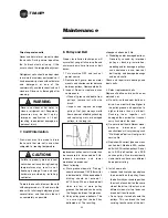
To measure belt tension, use a belt
tensioner as shown in Figure 18.
Determine actual deflection by
depressing one belt with the belt
tensioner and measuring the
deflection relative to the other belts or
to belt line. Adjust the belt tension to
the correct force (Newton) and tighten
all setscrews to the proper torques.
Figure 17
Belt Tension Measurement
Maintenance
Note:
Store belts in a cool, dry place
out of direct sunlight.
Types of sheave and shaft misalignment
Horizonal Angular
Vertical Angular
Parrallel
Align with straightedge along
sheave faces
DEFLECTION = SPAN mm X 15/1000mm
Summary of Contents for TRANE Quantum CLCPEuro
Page 2: ...TRANE R...
Page 6: ...TRANE R 2 CLCPXP Model Nomenclature...
Page 7: ...TRANE R CLCPEURO Model Nomenclature 3...
Page 13: ...TRANE R Assembly Installation CLCPEuro CLCPXP External connection 9...
Page 14: ...TRANE R Assembly Installation CLCPEuro Break Point 25mm Frame to Frame 10...
Page 15: ...TRANE R 11 Assembly Installation CLCPEuro Break Point 25mm Panel to Frame...
Page 16: ...TRANE R 12 Assembly Installation CLCPEuro Break Point 2 50mm Frame to Frame...
Page 17: ...TRANE R Assembly Installation CLCPEuro Break Point 2 50mm Panel to Frame 13...
Page 18: ...TRANE R Assembly Installation CLCPEuro Paneling 14...
Page 19: ...TRANE R Assembly Installation CLCP XP Break Point 15...
Page 20: ...TRANE R Assembly Installation CLCP XP Break Point 16...
Page 21: ...TRANE R 17 Assembly Installation CLCP...
Page 22: ...TRANE R Assembly Installation CLCP 18...
Page 36: ...TRANE R Maintenance 32 Figure 18 Belt Tension Measurement...
Page 39: ...TRANE R 35 Trouble Analysis Pulley and Belt...
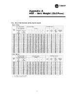
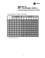
Page 45: ...TRANE R Appendix B HDT Unit Weight CLCPXP 41...
Page 46: ...TRANE R Appendix B HDT Unit Weight CLCPXP 42...
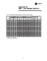
Page 47: ...TRANE R Appendix B HDT Unit Weight CLCPXP 43...
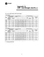
Page 48: ...TRANE R Appendix B VDT Unit Weight CLCPXP 44...
Page 53: ...TRANE R Appendix D Filter and Quantity 49 Filter Dimension and Arrangement Final Filter HEPA...
Page 57: ...TRANE R Typical Wiring Diagram Starter Star Delta 380 420V 3Phase 4Wires ELCB Standard 53...
Page 58: ...TRANE R 54 Typical Wiring Diagram Starter Dol 380 420V 3Phase 4Wires ELCB Standard...
Page 59: ...TRANE R 55 Typical Wiring Diagram Starter Dol 380 420V 3Phase 4Wires Standard...
Page 62: ...TRANE R 58 Typical Wiring Diagram Starter Dol 380 420V 3Phase 4Wires Standard...
Page 65: ...TRANE R 61 Typical Wiring Diagram Starter Star Delta 380 420V 3Phase 4Wires Standard...
Page 68: ...TRANE R 64...
Page 70: ...TRANE R 66...
Page 71: ...TRANE R...


