TRANE
R
General Information
• Foreword
These installations, operation and
maintenance instructions are given as
a guide to good practice in the
installation, commission into service,
operation and periodic maintenance
by the user, of TRANE Quantum
TM
Air
Handler. They do not contain full
service procedures necessary for the
continued successful operation of this
equipment; the services of a qualified
technician should be employed
through the medium of a maintenance
contract with a reputable service
company.
• Warranty
Trane’s standard warranty covers the
equipment. It does not cover damage
due to misuse, lack of maintenance,
or failure to comply with the
manufacturer’s instructions or
recommendations.
• Unit Description
TRANE Quantum
TM
Air Handler are
Central Station Air Handlers designed
for a variety of controlled air application.
The basic unit consists of a fan,
heating and/or cooling coils, filters and
air dampers. See product catalogue for
list of available modules and options.
The TRANE Quantum
TM
Air Handler are
designed for cooling load conditions
of 1000-65000 nominal CFM. Fans are
double width, double inlet, centrifugal
types with forward curved, backward
curved, and airfoil blade designs.
To insure fan motor assembly stability
the unit ships with shipping brackets
located between the fan support frame.
These spacers must be removed prior
to fan operation, to assure proper
vibration isolation.
Units ship as complete units, sections
or subassemblies. Each section is
provided with a nameplate (label)
which includes type of section, unit
serial number, customer tag number
and unit model number.
1
Summary of Contents for TRANE Quantum CLCPEuro
Page 2: ...TRANE R...
Page 6: ...TRANE R 2 CLCPXP Model Nomenclature...
Page 7: ...TRANE R CLCPEURO Model Nomenclature 3...
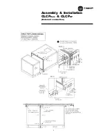
Page 13: ...TRANE R Assembly Installation CLCPEuro CLCPXP External connection 9...
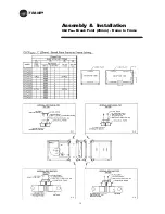
Page 14: ...TRANE R Assembly Installation CLCPEuro Break Point 25mm Frame to Frame 10...
Page 15: ...TRANE R 11 Assembly Installation CLCPEuro Break Point 25mm Panel to Frame...
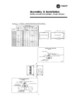
Page 16: ...TRANE R 12 Assembly Installation CLCPEuro Break Point 2 50mm Frame to Frame...
Page 17: ...TRANE R Assembly Installation CLCPEuro Break Point 2 50mm Panel to Frame 13...
Page 18: ...TRANE R Assembly Installation CLCPEuro Paneling 14...
Page 19: ...TRANE R Assembly Installation CLCP XP Break Point 15...
Page 20: ...TRANE R Assembly Installation CLCP XP Break Point 16...
Page 21: ...TRANE R 17 Assembly Installation CLCP...
Page 22: ...TRANE R Assembly Installation CLCP 18...
Page 36: ...TRANE R Maintenance 32 Figure 18 Belt Tension Measurement...
Page 39: ...TRANE R 35 Trouble Analysis Pulley and Belt...
Page 45: ...TRANE R Appendix B HDT Unit Weight CLCPXP 41...
Page 46: ...TRANE R Appendix B HDT Unit Weight CLCPXP 42...
Page 47: ...TRANE R Appendix B HDT Unit Weight CLCPXP 43...
Page 48: ...TRANE R Appendix B VDT Unit Weight CLCPXP 44...
Page 53: ...TRANE R Appendix D Filter and Quantity 49 Filter Dimension and Arrangement Final Filter HEPA...
Page 57: ...TRANE R Typical Wiring Diagram Starter Star Delta 380 420V 3Phase 4Wires ELCB Standard 53...
Page 58: ...TRANE R 54 Typical Wiring Diagram Starter Dol 380 420V 3Phase 4Wires ELCB Standard...
Page 59: ...TRANE R 55 Typical Wiring Diagram Starter Dol 380 420V 3Phase 4Wires Standard...
Page 62: ...TRANE R 58 Typical Wiring Diagram Starter Dol 380 420V 3Phase 4Wires Standard...
Page 65: ...TRANE R 61 Typical Wiring Diagram Starter Star Delta 380 420V 3Phase 4Wires Standard...
Page 68: ...TRANE R 64...
Page 70: ...TRANE R 66...
Page 71: ...TRANE R...


