background image

18-GE01D1-9

11

Installer’s Guide

H

B

A

W

3.70

2.50

19.50

.50

1.00

21.00

1.50

*

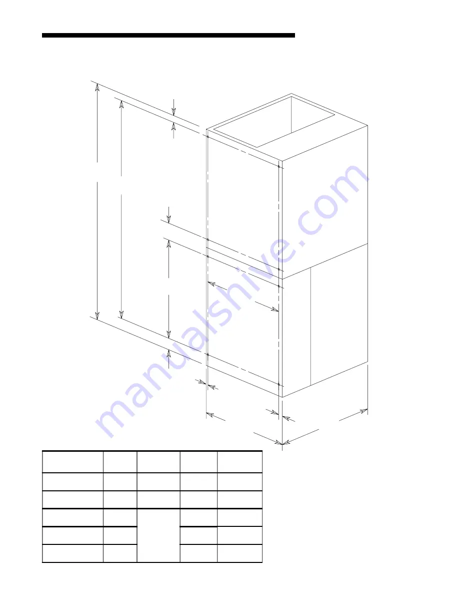
CAGE NUT MOUNTING LOCATION FOR TWE AIR HANDLERS

*

 FOR TWO PIECE

   CABINET ONLY.

Model No.

H

W

A

B

TWE031E13

43.00

21.50

17.00

39.00

TWE037E13

45.00

23.50

19.00

41.00

TWE040E13

51.75

26.00

23.80

47.75

TWE049E13

57.90

29.00

53.90

TWE065E13

62.75

31.25

58.75

Summary of Contents for TWE031E13FB1

Page 1: ...on and are fully con vertible to downflow or horizontal left Refer to Section B beginning on page 3 for additional information INSPECTION Check carefully for any shipping damage This must be re ported...

Page 2: ...r or by oth ers then installation of the air handler must be made to allow access for refrigerant lines or attach refrigerant lines to air handler when installing a fossil fuel device be installed and...

Page 3: ...ee Figure 3 c Position unit on Pedestal or other suitable foun dation If Pedestal is not used a frame strong enough to support the total weight must be pro vided Provide a minimum height of 14 inches...

Page 4: ...shown in the outline drawing HORIZONTAL LEFT a For maximum efficiency and Customer ease of filter maintenance it is recommended that a prop erly sized remote filter and grille be installed for horizo...

Page 5: ...ush fit for 3 4 or 1 1 2 duct board applications see the Outline drawing on page 10 for sizes of the duct connections After the duct is secured seal around the supply duct to prevent air leakage NOTE...

Page 6: ...imary drain See Figure 6 Two secondary drain connections are provided for the different orientations See Figure 6 The lower of the two should be connected as a backup to prevent conden sate overflow b...

Page 7: ...SWITCHES AS SHIPPED COOLING HEATING AIRFLOW FAN OFF DELAY AUXILIARY HEAT SPEEDS 0 OFF OFF 50 80 100 if necessary 50 Dehumidify Fast Coil Cooling and Heating Efficiency 7 5 minutes 3 minutes 1 minute...

Page 8: ...8 18 GE01D1 9 Installer s Guide TWE E AIR HANDLERS WITH SINGLE STAGE COOLING 2 STAGE HEAT TWE E AIR HANDLERS WITH TWO STAGE COOLING 2 STAGE HEAT From Dwg No B801074...

Page 9: ...the unit 3 Field wiring diagrams are provided which show the low voltage wiring hookup for a single speed cooling only system with supplementary heaters and a heat pump system with supplementary heat...

Page 10: ...STIBLE MATERIAL REQUIRED SERVICE CLEARANCE RECOMMENDED SIDES 0 2 FRONT 0 21 BACK 0 0 INLET DUCT 0 1 OUTLET DUCT 1 1 FOR THE FIRST 3 FT OF OUTLET DUCT WHEN ELECTRIC HEATERS ARE INSTALLED EXCEPT MODELS...

Page 11: ...0 21 00 1 50 CAGE NUT MOUNTING LOCATION FOR TWE AIR HANDLERS FOR TWO PIECE CABINET ONLY Model No H W A B TWE031E13 43 00 21 50 17 00 39 00 TWE037E13 45 00 23 50 19 00 41 00 TWE040E13 51 75 26 00 23 80...

Page 12: ...e that grounding of unit is in accord with code 3 Make sure unit suspension if used is secure and that there are no tools or loose debris in around or on top of the unit 4 Check all duct outlets they...

Reviews: