6
18-HD66D1-4
Preparation
Mount Panel
Section 3. Installation
The unit’s rugged design allows installation in closet, attic or other non-condensing locations free from
obstructions or other hazards.
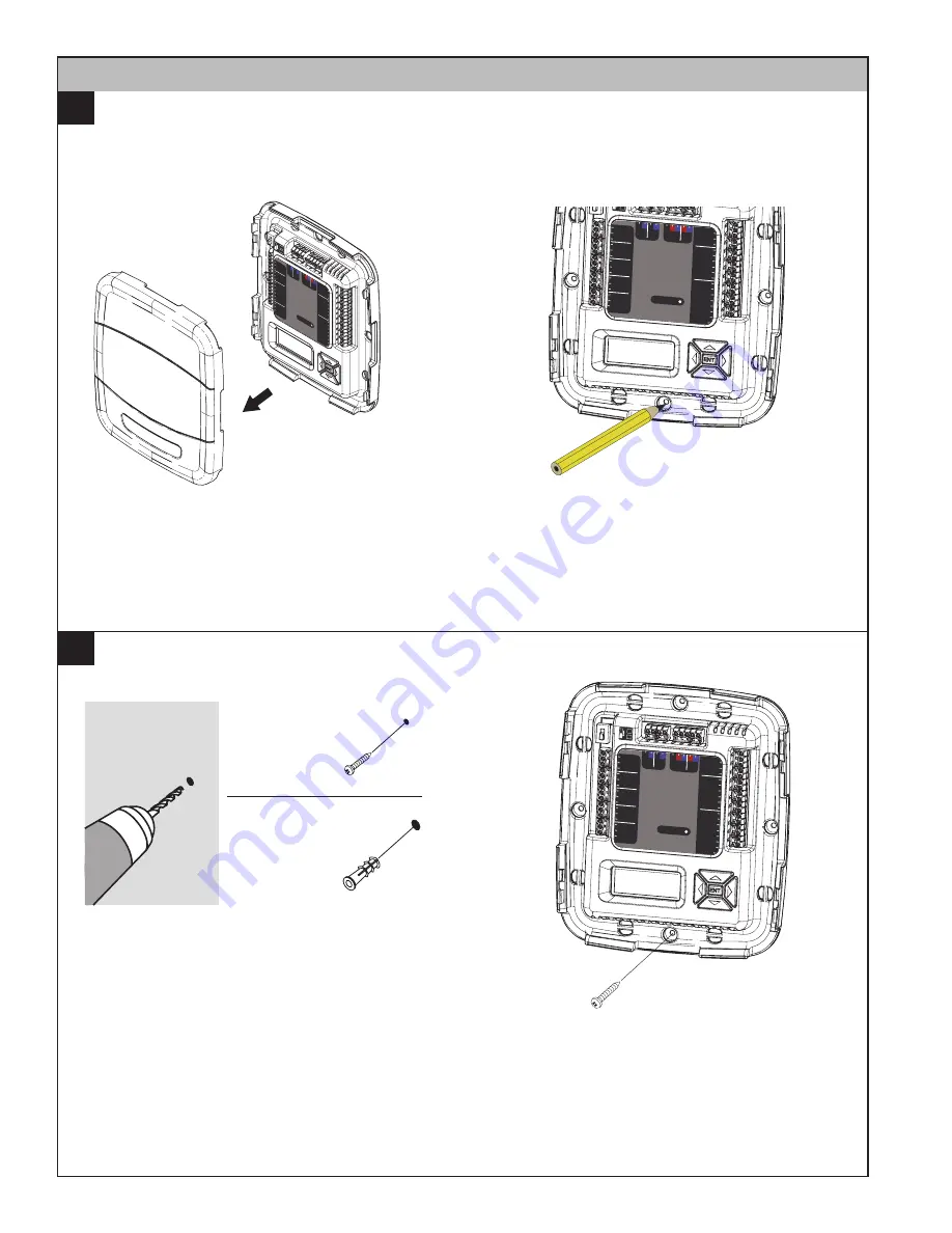
Remove cover by grasping at edges and gently
pulling the cover straight towards you. It should
release without much effort.
Mark four holes on the wall using the base as a
template. A level may be used to ensure accuracy.
Mounting to studs:
Drill 1/8” pilot holes in the four
locations marked above.
Mounting to drywall:
If mounting to drywall with no studs behind it,
enlarge pilot holes to 3/16” for anchors (included
with the control).
Gently tap anchors into the holes.
Attach base to wall using four screws provided.
Do not overtighten.
1/8” for screws
into studs
3/16” for drywall
anchors
DRILL HOLES
1A
1B
Zone Pane
l
ZO
NE
S 1 - 4
5 - 8
Zone Da
m
pers
Se
ns
or
s
Reser
ved
Rese
rved
Rese
rved
St
at
ic
P
re
ss
Gnd/Gr
n
Signa
l/Blk
+5V/Re
d
Te
m
pe
ra
tu
re
Non Comm Zone Senso
r
Disch
arge A
ir
Disch
arge A
ir
Retur
n Air
Retur
n Air
Mixed
Air
Mixed
Air
Zone
1 or 5
Zone
1 or 5
Zone
2 or 6
Zone
2 or 6
Zone
3 or 7
Zone
3 or 7
Zone
4 or 8
Zone
4 or 8
Zone 1 or
5
Indoo
r/
Relay
Pane
l Comm
Outd
oor
Com
m Zo
ne Se
nsor/
2nd Z
one P
anel
24V
Tran
s.
Com
mon
PO/O
pen
PC/C
losed
Zone 2 or
6
Com
mon
PO/O
pen
PC/C
losed
Zone 3 or
7
Com
mon
PO/O
pen
PC/C
losed
Zone 4 or
8
Com
mon
PO/O
pen
PC/C
losed
Comm
R
B
D
B
B
R
B
D
D
Zone Damper
s
Se
ns
or
s
Reserved
Reserved
Reserved
St
at
ic
P
re
ss
Gnd/Grn
Signal/Blk
+5V/Red
Tem
pe
ra
tu
re
Non Comm Z
one Sensor
Discharge Air
Discharge Air
Return Air
Return Air
Mixed Air
Mixed Air
Zone 1 or 5
Zone 1 or 5
Zone 2 or 6
Zone 2 or 6
Zone 3 or 7
Zone 3 or 7
Zone 4 or 8
Zone 4 or 8
Zone 1 or
5
Indoor/
Relay Panel Outdoor
Comm Zone Sensor/
2nd Zone Panel
24V
Trans.
Common
PO/Open
PC/Closed
Zone 2 or
6
Common
PO/Open
PC/Closed
Zone 3 or
7
Common
PO/Open
PC/Closed
Zone 4 or
8
Common
PO/Open
PC/Closed
Comm
R
B
D
B
B R B
D
D
ZO
NE
S
1 - 4
5 - 8
Zone Damper
s
Se
ns
or
s
Reserved
Reserved
Reserved
St
at
ic
P
re
ss
Gnd/Grn
Signal/Blk
+5V/Red
Tem
pe
ra
tu
re
Non Comm
Zone Sensor
Discharge Air
Discharge Air
Return Air
Return Air
Mixed Air
Mixed Air
Zone 1 or 5
Zone 1 or 5
Zone 2 or 6
Zone 2 or 6
Zone 3 or 7
Zone 3 or 7
Zone 4 or 8
Zone 4 or 8
Zone 1 or
5
Indoor/
Relay Panel Comm
Outdoor
Comm Zone Sensor/
2nd Zone Panel
24V
Trans.
Common
PO/Open
PC/Closed
Zone 2 or
6
Common
PO/Open
PC/Closed
Zone 3 or
7
Common
PO/Open
PC/Closed
Zone 4 or
8
Common
PO/Open
PC/Closed
Comm
R
B
D
B
B R B
D
D
ZO
NE
S
1 - 4
5 - 8


