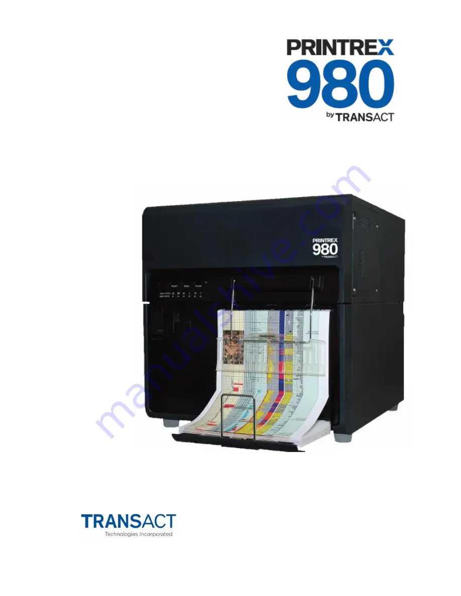
background image


Operators Guide 


100-11672 Rev D, September 2013 

Summary of Contents for Printrex 980

Page 1: ...Operators Guide 100 11672 Rev D September 2013...

Page 2: ...This page intentionally left blank...

Page 3: ...nges Date Rev A Initial release September 2012 Rev B Various updates and corrections January 2013 Rev C Add OEM installation and troubleshooting content August 2013 Rev D Changed Installing the Mainte...

Page 4: ...Page ii 100 11672 Rev D This page intentionally left blank...

Page 5: ...e the user will be required to correct the interference at his own expense Changes or modifications not expressly approved by TransAct Technologies Inc could void the user s authority to operate the e...

Page 6: ...FROM ANY ERRORS OMISSIONS OR DISCREPANCIES IN THE INFORMATION CONTAINED IN THIS DOCUMENT TransAct cannot guarantee that changes in software and equipment made by other manufacturers and referred to in...

Page 7: ...inter and Accessories 13 Ink Tank and Maintenance Cartridges 14 Step by Step Installation Procedures 15 How to Read This Procedure 17 When Using the Included Parts 17 About the Symbols Used in Illustr...

Page 8: ...ions 94 Electrical Specifications 95 Media Specifications 95 Paper 95 USB Interface 95 Printer Maintenance 97 Cleaning the Printer 99 Clearing Paper Jams 104 Moving the printer 106 Shipping the Printe...

Page 9: ...Adjustment 174 Head Position Fine Adjustment 178 Error Codes 184 Service Call Error Fatal Error 184 Operator Call Error 207 Warning 213 Installing the Maintenance Tool Service Utility 215 Operation Pr...

Page 10: ...Page viii 100 11672 Rev D Slow To Print 284 Print Quality Is Poor 284 Appendix A Ordering Supplies 285 Drivers Available 285 Index 287...

Page 11: ...100 11672 Rev D Page 1 Chapter 1 Introducing your Printrex 980 Printer...

Page 12: ...Page 2 100 11672 Rev D This page intentionally left blank...

Page 13: ...cond plot speed No limitation on plot length allowing plotting of continuous logs Print quality enhancement features including o Depth Line Accuracy ensuring accuracy of scale o Stitching Stream Techn...

Page 14: ...printer It provides the following information to support your installation and operational efforts Warranty and technical support information Specifications and functionality description Installation...

Page 15: ...ransact tech com Telephone Technical Support Live telephone support is available by contacting Printrex or one of its regional affiliates via the contact information listed in this section To help us...

Page 16: ...erial Do not return any accessories unless asked to do so by a support technician Write the RMA number clearly on the outside of the box Shipping Printers Never ship a printer by any means with any in...

Page 17: ...l Support fax 607 257 3911 Web site www transact tech com Western United States 877 822 8923 Fax 702 254 7796 United Kingdom 011 44 170 977 2500 Fax 011 44 170 977 2505 R Associates Inc 6610 Gant Road...

Page 18: ...Web Site www elkutec de Email sales elkutec de China Star Luck Enterprises Inc Beijing Office Room 328 Grand Vision Business Building No 2 Jiuxianqiao Road Chaoyang District Beijing 100015 China Telep...

Page 19: ...100 11672 Rev D Page 9 Chapter 2 Safety Precautions...

Page 20: ...Page 10 100 11672 Rev D This page intentionally left blank...

Page 21: ...d or falls this could cause personal injury Never expose the printer to open air or dust This could cause a fire serious electrical shock or damage to the printer Also never locate the printer near a...

Page 22: ...wer cord from the printer and the power supply and use a soft dry cloth to clean the cord connectors and the connection points Leaving the cord plugged in and not cleaned for a long period especially...

Page 23: ...amage the printer If something falls into the printer accidentally switch the printer off immediately disconnect the power plug from the power source and call for service If the printer is dropped and...

Page 24: ...reach of small children This prevents accidents If a child accidentally swallows ink seek medical attention immediately If ink gets into your eyes wash it out with flowing water immediately If irrita...

Page 25: ...100 11672 Rev D Page 15 Chapter 3 Step by Step Installation Procedures...

Page 26: ...Page 16 100 11672 Rev D This page intentionally left blank...

Page 27: ...the Included Parts in this Guide When the parts supplied with this product are required to be used in the installation procedure the following symbol indicating that the parts are supplied with the pr...

Page 28: ...rature range 5 to 35 degrees celsius Operating humidity range 10 RH to 90 RH 3 Avoid installing the printer near a fire in a dusty place or in a place where ammonia gas is generated When installing th...

Page 29: ...Step by Step Installation Instructions 100 11672 Rev D Page 19 Checking the Installation Space 1 The minimum space required for installation and maintenance is shown below...

Page 30: ...ensation can occur when the printer is moved from a low temperature place to a high temperature installation place In such a case leave the printer as it stands for at least 2 hours until it adjusts t...

Page 31: ...Step by Step Installation Instructions 100 11672 Rev D Page 21 Unpacking Printer and Checking the Components 1 Check that the following parts are included...

Page 32: ...vibrations and shocks applied during transportation By following the procedure described below remove all pieces of fixing tape and cushioning materials before installing the printer Keep the removed...

Page 33: ...ctions 100 11672 Rev D Page 23 3 Lift either side of the printer temporarily to remove the 2 lower pads Next lift the other side of the printer to remove the remaining 2 lower pads 4 Strip the plastic...

Page 34: ...ons Page 24 100 11672 Rev D 5 Holding the handles at the bottom of the printer lift the printer to take it out from the package base Caution At least 3 persons are required to lift the printer Do not...

Page 35: ...ushioning material visible on the exterior of the printer 7 Open Ink Tank Door and then push Upper Unit Open Lever to open Upper Unit 8 Remove all pieces of fixing tape and cushioning material around...

Page 36: ...Step by Step Installation Instructions Page 26 100 11672 Rev D 9 Close Upper Unit and Ink Tank Door...

Page 37: ...Step by Step Installation Instructions 100 11672 Rev D Page 27 Mounting Rear Feeder Guide 1 Mount the included Rear Feeder Guide on Rear Feeder Slot of Printer using 2 included screws TP screws M4 8...

Page 38: ...ation Instructions Page 28 100 11672 Rev D Loading Ink Tanks 1 Open Ink Tank Door 2 Open Ink Tank Lever for each color while pushing it downward 3 Take included Ink Tank out of Package and then remove...

Page 39: ...k Tank as far as it will go Caution Ink Tank cannot be loaded properly if it is inserted in the wrong Ink Tank Slot Insert Ink Tank securely and push it all the way as far as it will go 5 Close Ink Ta...

Page 40: ...uired for initial ink loading When initial ink loading is completed the STATUS lamp lights and not blinking Make sure that the STATUS lamp lights before proceeding to the next step Caution Do not turn...

Page 41: ...ter operation and the lamps that indicate printer status 3 Power switch Use this switch when the printer is scheduled to be unused for a long period of time or it is relocated 4 Ink tank door Open thi...

Page 42: ...o the computer 2 USB port Connect a USB cable here to connect to the computer 3 Rear feeder slot This slot is used to feed paper exceeding the paper tray capacity 4 Rear Feeder Guide This component is...

Page 43: ...t 2 Paper tray Load paper in this tray 3 Lift button for paper tray Pressing this button moves the paper tray up and down 4 Ink tanks Black Bk Cyan C Magenta M and Yellow Y ink tanks are loaded 5 Tran...

Page 44: ...ey Pressing this key down for about 1 second during printing cancels all jobs to abort printing 3 FEED key Pressing this key in the offline mode feeds paper 4 ONLINE key Pressing this key suspends res...

Page 45: ...rator call error can be recovered by user operation Blinking Fatal error Off Normal 10 STATUS lamp On Online mode Blinking Data being received printing cleaning initializing shut down Off Printing is...

Page 46: ...ct the USB cable in the cases described below This could prevent the printer from operating normally While the computer is starting up until the desktop display appears While the printer is printing W...

Page 47: ...e figure and then the computer Note Please consult your network administrator when connecting to an office LAN Note If a printer driver has not been installed in the computer to which you want to conn...

Page 48: ...100 11672 Rev D 2 The STATUS lamp stays lit Note When the printer is in the sleep mode press the power key to return the printer to Online mode Printer will also wake up from the sleep mode automatica...

Page 49: ...Page 39 Switching the Printer Off 1 Press the power key for a few seconds more than one second Power lamp blinks and the printer enters the sleep mode 2 Turn off the power switch If the printer is al...

Page 50: ...ibes how to load paper 1 Make sure that the Power key lamp on the operation lamp stays lit If the printer has been turned off completely turn on the main power switch When the printer is in the sleep...

Page 51: ...Step by Step Installation Instructions 100 11672 Rev D Page 41 4 Open the upper unit 5 Press the lift button for paper tray The paper tray moves up...

Page 52: ...on Instructions Page 42 100 11672 Rev D Note Do not touch the lifting mechanism while the paper tray is moving up down Your fingers could be caught in the machine and this could cause injury 6 Draw ou...

Page 53: ...Step by Step Installation Instructions 100 11672 Rev D Page 43 7 Load paper in the paper tray Load paper with the black mark located on the tip right side of the back of the printing surface...

Page 54: ...After loading paper push the paper tray all the way 9 Press the lift button for paper tray to move the paper tray down Note Follow the same procedure when replacing paper When the paper tray has been...

Page 55: ...Step Installation Instructions 100 11672 Rev D Page 45 10 When the paper tray has moved down completely draw out the stacker unit then raise the bar 11 Pull out paper and then place paper on the stack...

Page 56: ...paper in transport area place it against paper guides on the right side Set paper such that it is not slackened Note Largely slack paper can jam To prevent this pull out paper over the transport unit...

Page 57: ...in personal injury 13 Paper is automatically fed to the printing position Note Load paper in printer immediately after unpacking it Paper remaining after completion of printing may be held loaded in p...

Page 58: ...rinter 1 Make sure that the Power key lamp on the operation lamp stays lit If the printer has been turned off completely turn on the power switch When the printer is in the sleep mode press the Power...

Page 59: ...Step by Step Installation Instructions 100 11672 Rev D Page 49 4 Open the upper unit 5 When the paper tray has moved down completely draw out the stacker unit then raise the bar...

Page 60: ...he printer Note When supplying paper from the rear of printer place the paper storage box containing paper below Feeder Slot at the back of printer at a height that is 100 820 mm lower than Feeder Slo...

Page 61: ...Step by Step Installation Instructions 100 11672 Rev D Page 51 7 Pull out paper from the paper tray 8 Pull out paper and then place paper on the stacker unit...

Page 62: ...paper in transport area place it against paper guides on the right side Set paper such that it is not slackened Note Largely slack paper can jam To prevent this pull out paper over the transport unit...

Page 63: ...in personal injury 10 Paper is automatically fed to the printing position Note Load paper in printer immediately after unpacking it Paper remaining after completion of printing may be held loaded in p...

Page 64: ...kage Do not remove an ink tank unless you must replace it This could shorten the life of the consumables Complete the ink tank replacement procedure as quickly as possible Do not leave the printer wit...

Page 65: ...Step by Step Installation Instructions 100 11672 Rev D Page 55 1 Open the ink tank door 2 Pull the lever down...

Page 66: ...3 Remove the empty ink tank Note Do not touch the ink outlet and terminal to prevent soiling of the the surrounding work area damage to the ink tank and poor printing Note Never apply excessive force...

Page 67: ...100 11672 Rev D Page 57 4 Slowly insert a new ink tank all the way 5 Close the ink tank lever securely Note There are sharp pins in ink tank slots Never put your fingers into this area This could caus...

Page 68: ...g an ink tank do not remove it unless you must replace it This could shorten the life of the consumables Complete the ink tank replacement procedure as quickly as possible Do not leave the printer wit...

Page 69: ...keep the Maintenance Cartridge out of the reach of children If ink is accidentally ingested contact a physician immediately Note To prevent ink from leaking from a used Maintenance Cartridge avoid dro...

Page 70: ...stallation Instructions Page 60 100 11672 Rev D 2 Draw out the maintenance cartridge slowly 3 Take out new maintenance cartridge from a box 4 While lifting the eject guide slightly insert a new mainte...

Page 71: ...guide slightly close the maintenance cartridge door 6 Put the used maintenance cartridge in a bundled plastic bag and dispose of it Note Please dispose the old maintenance cartridge according to feder...

Page 72: ...an adjustment procedure corresponding to each test print Nozzle check pattern TK GAP adjustment pattern Slant Adjustment Pattern Head Position Adjustment Pattern Printing and Examining Nozzle Check Pa...

Page 73: ...Step by Step Installation Instructions 100 11672 Rev D Page 63 4 Open the Test Print Adjustment tab of the 980 Service Utility dialog box 5 Click Nozzle Check Pattern to print the nozzle check pattern...

Page 74: ...p by Step Installation Instructions Page 64 100 11672 Rev D 6 Check the printed nozzle check pattern If a non discharge is detected perform cleaning with reference to the next section Cleaning Procedu...

Page 75: ...Step by Step Installation Instructions 100 11672 Rev D Page 65 Cleaning Procedure 1 Open the Cleaning User Setting tab of the 980 Service Utility dialog box 2 Select Print Module to be cleaned...

Page 76: ...Light Cleaning About 0 5 minutes If an ink injection problem is detected perform Light Cleaning first If the problem persists even after Light Cleaning is performed several times perform Medium Cleani...

Page 77: ...Instructions 100 11672 Rev D Page 67 Printing TK GAP Adjustment Pattern 1 Open the Test Print Adjustment tab and click Adjust TK GAP to display the Print TK GAP dialog box 2 Click Print to print the...

Page 78: ...tern and examine if the TK GAP adjustment is necessary for Print Modules according to the following Perform the adjustment if necessary Find where the paper perforation is located on the TK GAP adjust...

Page 79: ...ues in the TK GAP adjustment value entry boxes in the Print TK GAP dialog box 3 After entering the TK GAP adjustment values click Send to send the adjustment values to Printer 4 If the TK GAP adjustme...

Page 80: ...Step by Step Installation Instructions Page 70 100 11672 Rev D 5 If the TK GAP adjustment pattern is desired for reviewing click Yes 6 Click Next to proceed to the slant adjustment...

Page 81: ...Instructions 100 11672 Rev D Page 71 Printing Slant Adjustment Pattern 1 Open the Test Print Adjustment tab and click Adjust Slant to display the Print Head Slant dialog box 2 Click Print to print the...

Page 82: ...ach color Cyan Magenta or Yellow When a value of A is the same as a value of B Example 1 When the value of C1A 2 is the same as the value of C1B 2 no adjustment is required for C1 Cyan Printhead 1 Whe...

Page 83: ...alues in the slant adjustment value entry boxes in the Print Head Slant dialog box 3 After entering the slant adjustment values click Send to send the adjustment values to Printer 4 If the slant adjus...

Page 84: ...Step by Step Installation Instructions Page 74 100 11672 Rev D 5 If the slant adjustment pattern is desired for reviewing click Yes 6 Click Next to proceed to the head position adjustment...

Page 85: ...Installation Instructions 100 11672 Rev D Page 75 Printing Head Position Adjustment Pattern 1 Open the Test Print Adjustment tab and click Adjust Position to display the Print Head Position Adjustmen...

Page 86: ...Step by Step Installation Instructions Page 76 100 11672 Rev D 2 Click Print to print the head position adjustment pattern...

Page 87: ...Modules to each other The relative print positions in the feeding direction can be examined in the KV scale For the example shown in the figure the 2 elements are in line at 2 Thus the adjustment val...

Page 88: ...all the printheads The relative color registrations in the feeding direction can be examined in the xxV scale and the ones in the cross feeding direction can be examined in the xxH scale Determine at...

Page 89: ...Step by Step Installation Instructions 100 11672 Rev D Page 79 3 Enter adjustment values in the Module to Module adjustment value entry boxes in the Print Head Position Adjustment dialog box...

Page 90: ...Step by Step Installation Instructions Page 80 100 11672 Rev D 4 Click Go to Step 3...

Page 91: ...Step by Step Installation Instructions 100 11672 Rev D Page 81 5 Enter the adjustment values in the Head Position Adjustment value entry boxes...

Page 92: ...Step by Step Installation Instructions Page 82 100 11672 Rev D 6 Click Go to Step 4...

Page 93: ...Step by Step Installation Instructions 100 11672 Rev D Page 83 7 Enter the adjustment values in the Head Position Adjustment value entry boxes...

Page 94: ...ev D 8 Click Send to send all the adjustment values to Printer 9 If the head position adjustment pattern is not required to print again for a review click NO and proceed to step 10 10 If the head posi...

Page 95: ...Step by Step Installation Instructions 100 11672 Rev D Page 85 11 Press Power Key for at least 1 second to place Printer in the sleep mode Power Lamp blinks and then turn off Main Power Switch...

Page 96: ...expected failures when Printer is transported Caution Do not incline Printer more than 15 degrees during relocation Relocating from One Place to Another on Same Floor or in Same Building Printer requi...

Page 97: ...e to the specification change Long Distance Relocation Printer required to return ink from Print Module to Ink Tank and to drain suction remaining ink in Purge Unit before shipping Printer long distan...

Page 98: ...displayed click Yes to start return ink from Print Module to Ink Tank and wait for a while Note Ink returning and drainage takes approx 20 minutes The time might be changed due to the specification c...

Page 99: ...Step by Step Installation Instructions 100 11672 Rev D Page 89 5 When the following message is displayed turn off Main Power Switch...

Page 100: ......

Page 101: ...100 11672 Rev D Page 91 Chapter 4 Printrex 980 Specifications and Requirements...

Page 102: ...Page 92 100 11672 Rev D This page intentionally left blank...

Page 103: ...ontal 600 dots per inch vertical No limitation on plot length allowing plotting of continuous logs Print quality enhancement features including o Depth Line Accuracy ensuring accuracy of scale o Stitc...

Page 104: ...800 is designed to be placed on a flat stable surface that can support the weight of the printer about 123 lbs or 56 kg Be aware that the environmental conditions of the location where you place the p...

Page 105: ...he USB interface is a Version 2 0 interface card is implemented through a standard Series B receptacle as defined in the USB Specification The printer is self powered and does not draw power from the...

Page 106: ......

Page 107: ...100 11672 Rev D Page 97 Chapter 5 Printer Maintenance...

Page 108: ...Page 98 100 11672 Rev D This page intentionally left blank...

Page 109: ...clean the exterior covers of the printer Note Use only a slightly damp cloth thoroughly wrung out to clean the printer interior Never use alcohol thinner benzene or any other flammable liquids This c...

Page 110: ...How to Operate the Printrex 980 Printer Page 100 100 11672 Rev D 2 Turn off the main power switch and then remove the power plug from the wall outlet 3 Open the ink tank door...

Page 111: ...How to Operate the Printrex 980 Printer 100 11672 Rev D Page 101 4 Push the upper unit release lever up to open the Upper unit 5 Open the upper unit...

Page 112: ...cloth dipped in water and tightly wrung out Note Do not clean the printer with tissues or paper towels Torn pieces of paper or paper dust may get inside the printer and cause malfunctions Note If Pape...

Page 113: ...How to Operate the Printrex 980 Printer 100 11672 Rev D Page 103 7 Close the upper unit and then close the ink tank door...

Page 114: ...while the printer is printing the printer will stop and the Status Monitor will display a paper jam message Follow the procedure below to remove the jammed paper 1 Open the ink tank door and then push...

Page 115: ...How to Operate the Printrex 980 Printer 100 11672 Rev D Page 105 3 Cut the paper along the perforation...

Page 116: ...it properly following the procedure described below 1 Press the Power key to place the printer in the sleep mode If the printer is already in sleep mode go to step 2 2 Press the main power switch belo...

Page 117: ...ving it this could cause a fire or serious electrical shock or damage the printer The printer weighs about 123 pounds 57kg Three persons are always required to move the printer When lifting and moving...

Page 118: ...How to Operate the Printrex 980 Printer Page 108 100 11672 Rev D 8 After completion of the initial operation the printer is ready for printing...

Page 119: ...the printer be sure to drain the printer of ink If ink tanks are removed before draining the printer of ink ink leaks from the needle sections in the ink tank slots could stain your clothes and surrou...

Page 120: ......

Page 121: ...100 11672 Rev D Page 111 Chapter 6 Troubleshooting...

Page 122: ...Page 112 100 11672 Rev D This page intentionally left blank...

Page 123: ...o avoid placement near fire or flame 5 Avoid dusty locations 6 Avoid the place exposed to direct sunlight If it is inevitable to install the printer in such a place instruct the customer to hang curta...

Page 124: ...the receiving of Rear Feeder Sensor and or Trailing Edge Sensor Those reflecting plates need to be cleaned Rear Feeder Sensor Cleaning 1 Remove Right Cover Removing Right Cover section 2 Remove Left...

Page 125: ...Appendix A Ordering Genuine Ithaca Supplies 100 11672 Rev D Page 115 Trailing Edge Sensor Cleaning 1 Open Upper Unit 2 Wipe reflecting plate with a cotton swab...

Page 126: ...printing are described below When an image defect is found carry out test printing to determine the image defect type and then perform an appropriate procedure Vertical White Streak Non Discharge This...

Page 127: ...ortion This is a state in which ink drops cannot be discharged from Printhead nozzles due to dust bubbles thickened ink wetting etc around Printhead nozzle or a state in which a condensed ink film is...

Page 128: ...Appendix B Frequently Asked Questions Page 118 100 11672 Rev D Void This is a state in which a void is generated due to defective parts of Printhead Flexible Cable PCB etc or a bad connection...

Page 129: ...enuine Ithaca Supplies 100 11672 Rev D Page 119 Abnormal Discharge This is a state in which ink is ejected to an area having no image data due to defective parts of the Printhead Flexible Cable PCB et...

Page 130: ...B Frequently Asked Questions Page 120 100 11672 Rev D Uneven Image Cross Feeding Direction This is a state in which stripes differing in thickness are generated in the longitudinal direction of the P...

Page 131: ...Appendix A Ordering Genuine Ithaca Supplies 100 11672 Rev D Page 121 Uneven Image Feeding Direction This is a state in which stripes differing in thickness are generated in the transport direction...

Page 132: ...tly Asked Questions Page 122 100 11672 Rev D Relative Misregistration in Colors in X or Y Direction This is a state in which registration positions of individual colors are deviated and as a result co...

Page 133: ...rdering Genuine Ithaca Supplies 100 11672 Rev D Page 123 Misregistration Leading edge and side edge Print image coordinate is not aligned with the paper The following sample shows misregistration in t...

Page 134: ...Appendix B Frequently Asked Questions Page 124 100 11672 Rev D Blank Image This is a state in which the print sheet is ejected with no image printed on it...

Page 135: ...Appendix A Ordering Genuine Ithaca Supplies 100 11672 Rev D Page 125 Paper Skew This is a state in which an image is printed on a skew in relation to the left and right edges of the print sheet...

Page 136: ...Appendix B Frequently Asked Questions Page 126 100 11672 Rev D Spur Marks White Dotted Lines This is a state in which pressed Spur marks are made on the print sheet...

Page 137: ...Appendix A Ordering Genuine Ithaca Supplies 100 11672 Rev D Page 127 Ink Smearing Due to Printhead Crash This is a state in which the print sheet touches the Printhead and is stained with ink...

Page 138: ...ed Questions Page 128 100 11672 Rev D Spur Marks Dotted Lines This is a state in which ink is transferred to Spur or Spur cleaner due to ink dripping fixing error etc and as a result Spur ink marks ar...

Page 139: ...aca Supplies 100 11672 Rev D Page 129 Ink Adhesion Ink Dripping This is a state in which ink collected in Printhead or Purge Unit drips off to transport area and as a result ink adheres to the front b...

Page 140: ...ule and then check that the defect has been recovered End Printer Controller PCB 7 Replace Printer Controller PCB and then check that the defect has been recovered End Void or Abnormal Discharge Test...

Page 141: ...rocedure 1 Service Utility Troubleshooting 2 Choose Print Module 1 and or 2 3 Click Head Install Position 4 Turn off the power 5 Remove covers 6 Rotate up Upper Printhead Release Lever until it stops...

Page 142: ...defect has been recovered End Printhead 2 Replace Printhead and then check that the defect has been recovered End Printer Controller PCB 3 Replace Printer Controller PCB and then check that the defect...

Page 143: ...Printhead 2 Printhead Unit is not assembled properly Reassemble it properly 3 Unit is not installed properly Reinstall it properly Pinch Roller Unit or Spur Unit 4 Unit is not installed properly Rein...

Page 144: ...d End TOF Sensor 7 TOF Sensor is contaminated with paper dust etc Clean TOF Sensor 8 TOF Sensor is not operating properly Replace TOF Sensor Paper Skew Cause Procedure Check Item Action Paper 1 Paper...

Page 145: ...Pinch Roller Unit or Spur Unit 2 The unit is not installed properly Reinstall it properly 3 Pinch Roller or Spur does not rotate smoothly Replace Pinch Roller Unit or Spur Unit Setup 4 The Printhead h...

Page 146: ...Cause Procedure Check Item Action Print Module 1 Print Module is not installed properly End Ink Supply System 2 Even when Medium Cleaning is carried out waste ink is not sucked from Purge Unit After...

Page 147: ...sition 2 Head Position Adjustment Backfeed gap Backfeed Gap Adjustment Rack Unit Rack position Work at Rack Unit Replacement Lift Unit Rear Feeder sensor Rear Feeder sensor Rear Feeder Sensor Adjustme...

Page 148: ...v D Head Position Adjustment This section describes the works to be carried out when adjusting the basic Head position Item Standard Value Reference T K gap adjustment 0 5 1 0mm Head Position Adjustme...

Page 149: ...ment Note Print Module adjustment procedure must be operate on a flat table Gap between Print Module and the table must be less than 0 5mm 1 Attach Print Module Joint Plate 1 to Print Module 2 when re...

Page 150: ...100 11672 Rev D 3 Adjust Print Modules in place Adjustment 1 1 Place two wrenches in a L shape to adjust the horizontal position Place the ruler against the end face of Print Module 2 Tighten the scr...

Page 151: ...Appendix A Ordering Genuine Ithaca Supplies 100 11672 Rev D Page 141 Adjustment 2 1 Place a wrench and Print Module Height Fixture B between Print Modules 1 and 2...

Page 152: ...42 100 11672 Rev D 2 Secure Print Modules 1 and 2 4 screws 3 Attach Print Module Height Fixture B 2 screws Note Do not rotate red screw When attaching Print Module Height Fixture B place it against th...

Page 153: ...s 100 11672 Rev D Page 143 4 Attach Print Module Top Plate 10 screws Adjustment Value Input 1 Input adjustment Values Print Module Replacement Procedure section Head Position Adjustment 1 Adjust Head...

Page 154: ...placement Head Position Adjustment 1 Adjust Head position Head Position Adjustment section Work at Purge Unit Replacement Blade Position Adjustment 1 Loosen the screw by 1 turn 2 Set the key pins on h...

Page 155: ...nch Roller Position Adjustment 1 Print backfeed pattern Backfeed Gap Adjustment page 5 92 2 Observe the backfeed pattern and examine if Pinch Roller adjustment is necessary according to the following...

Page 156: ...pattern have overlapped at right side shift the plate to A direction If the gray areas of backfeed pattern have overlapped at left side shift the plate to B direction Go to the Adjustment Procedure s...

Page 157: ...that located at center only Screws at both side support the plate of Pinch Roller 3 Shift the plate of Pinch Roller all the way and tighten the screw Head Position Adjustment 1 Adjust Head position He...

Page 158: ...Unit Replacement 1 Adjust Rack Unit at same position as noted number that was noted when Rack Unit was removed and then tighten screws Rear Feeder Sensor Adjustment 1 Insert paper in the feeder slot p...

Page 159: ...enuine Ithaca Supplies 100 11672 Rev D Page 149 2 Connect PC to Printer and then start service utility Open Parts Replacement tab and then click Adjust to adjust Rear Feeder Sensor 3 Confirm that Rear...

Page 160: ...Appendix B Frequently Asked Questions Page 150 100 11672 Rev D 4 Remove the paper from feeder slot provided on the back of Printer and then confirm that Rear Feeder Sensor is OFF...

Page 161: ...672 Rev D Page 151 Work at Stacker Rail and or Front Tray Unit Replacement 1 Prefix Front Tray Unit using screws 2 screws 2 Draw out Stacker Rail Until it stops and then put a bundle of fanfold paper...

Page 162: ...ce utility 2 Retrieve the date from Printer Controller PCB to PC Printer Controller PCB Replacement Procedure section After Printer Controller PCB Replacement In the case data can be retrieved from Pr...

Page 163: ...Module Replacement Procedure section 8 Adjust Rear Feeder Sensor Rear Feeder Sensor Adjustment section 9 Adjust ink eject power DC Power Supply Unit Replacement Procedure section 10 Adjust Printhead p...

Page 164: ...100 11672 Rev D Head Position Adjustment TK GAP Adjustment Printing TK GAP Adjustment Pattern 1 Connect PC to Printer and then start service utility Open the Test Print Adjustment tab and click Adjust...

Page 165: ...rve the TK GAP Adjustment Pattern and examine if the TK GAP adjustment is necessary for Print Modules according to the following Perform the adjustment if necessary Find where the paper perforation is...

Page 166: ...Appendix B Frequently Asked Questions Page 156 100 11672 Rev D 2 Enter the adjustment values in the TK GAP adjustment value entry boxes in the Print TK GAP dialog box...

Page 167: ...After entering the TK GAP adjustment values click Send to send the adjustment values to Printer 4 If the TK GAP adjustment pattern is not required to print again for a review click No and proceed to...

Page 168: ...v D 6 Click Next to proceed to the slant adjustment Slant Adjustment Printing Slant Adjustment Pattern 1 Connect PC to Printer and then start service utility Open the Test Print Adjustment tab and cli...

Page 169: ...Appendix A Ordering Genuine Ithaca Supplies 100 11672 Rev D Page 159 2 Click Print to print the slant adjustment pattern...

Page 170: ...ach color Cyan Magenta or Yellow When a value of A is the same as a value of B Example 1 When the value of C1A 2 is the same as the value of C1B 2 no adjustment is required for C1 Cyan Printhead 1 Whe...

Page 171: ...Appendix A Ordering Genuine Ithaca Supplies 100 11672 Rev D Page 161 2 Enter necessary adjustment values in the slant adjustment value entry boxes in the Print Head Slant dialog box...

Page 172: ...fter entering the slant adjustment values click Send to send the adjustment values to Printer 4 If the slant adjustment pattern is not required to print again for a review click No and proceed to step...

Page 173: ...Appendix A Ordering Genuine Ithaca Supplies 100 11672 Rev D Page 163 6 Click Next to proceed to the head position adjustment...

Page 174: ...11672 Rev D Head Position Adjustment Printing Head Position Adjustment Pattern 1 Connect PC to Printer and then start service utility Open the Test Print Adjustment tab and click Adjust Position to di...

Page 175: ...Appendix A Ordering Genuine Ithaca Supplies 100 11672 Rev D Page 165 2 Click Print to print the head position adjustment pattern...

Page 176: ...Modules to each other The relative print positions in the feeding direction can be examined in the KV scale For the example shown in the figure the 2 elements are in line at 2 Thus the adjustment val...

Page 177: ...ns in all Printheads The relative color registrations in the feeding direction can be examined in the xxV scale and the ones in the cross feeding direction can be examined in the xxH scale Determine a...

Page 178: ...Appendix B Frequently Asked Questions Page 168 100 11672 Rev D 3 Enter adjustment values in the Module to Module adjustment value entry boxes in the Print Head Position Adjustment dialog box...

Page 179: ...Appendix A Ordering Genuine Ithaca Supplies 100 11672 Rev D Page 169 4 Click Go to Step 3...

Page 180: ...Appendix B Frequently Asked Questions Page 170 100 11672 Rev D 5 Enter the adjustment values in the Head Position Adjustment value entry boxes...

Page 181: ...Appendix A Ordering Genuine Ithaca Supplies 100 11672 Rev D Page 171 6 Click Go to Step 4...

Page 182: ...Appendix B Frequently Asked Questions Page 172 100 11672 Rev D 7 Enter the adjustment values in the Head Position Adjustment value entry boxes...

Page 183: ...D Page 173 8 Click Send to send all the adjustment values to Printer 9 If the head position adjustment pattern is not required to print again for a review click No and proceed to step 10 10 If you wis...

Page 184: ...ked Questions Page 174 100 11672 Rev D Backfeed Gap Adjustment Printing Backfeed Pattern 1 Connect PC to Printer and then start service utility Open the Test Print Adjustment tab and click Print to pr...

Page 185: ...Examining and Adjusting Backfeed Gap 1 Observe the backfeed pattern and examine if the backfeed gap adjustment is necessary Perform the adjustment if necessary If the gray areas of the left and the ri...

Page 186: ...Appendix B Frequently Asked Questions Page 176 100 11672 Rev D If the gray areas of the left and the right end have overlaps and darken press the reduce overlap button...

Page 187: ...Genuine Ithaca Supplies 100 11672 Rev D Page 177 If the gray areas of the left and the right end have gap and or overlap less than 0 3mm adjustment is not required 2 Click Send to send the adjustment...

Page 188: ...review click No 4 If you wish to review the backfeed pattern click Yes and go to step 1 Head Position Fine Adjustment Printing Head Position Fine Adjustment Pattern 1 Connect PC to Printer and then st...

Page 189: ...nt Pattern and examine if the TK GAP adjustment is necessary for Print Modules according to the following Perform the adjustment if necessary Find where the paper perforation is located on the TK GAP...

Page 190: ...2 Enter the adjustment values in the TK GAP adjustment value entry boxes 3 Read numerical values of the lines which connected smoothly to magenta line for all the 54 sections from 1M1 to 2Y9 For examp...

Page 191: ...nd the minimum and maximum numerical values of Black line for each Print Module 1 and Print Module 2 For example minimum numerical value of Print Module 1 is 8 maximum numerical value of Print Module...

Page 192: ...ed Questions Page 182 100 11672 Rev D 6 Click Go to Step 4 7 Find minimum and maximum numerical values of Cyan and Yellow lines for each Print Module 1 and Print Module 2 and then enter the numerical...

Page 193: ...Appendix A Ordering Genuine Ithaca Supplies 100 11672 Rev D Page 183 8 Click Send to send data to Printer...

Page 194: ...ter needs to be some operation even though printing Using printer continually with warning may cause of operator call error Service Call Error Fatal Error Service call error refers to an error that ca...

Page 195: ...memory so the same error will recur next time Printer starts To clear the error Service Utility Parts Replacement Release the Error and then restart Printer 02 Power Supply Error 02 11 Condition Dete...

Page 196: ...lace Print Module 3 Replace Printer Controller PCB 05 62 MODULE1 E2 MODULE2 Condition Detected Printhead position error Action 1 Check Printhead Lifter part movement 2 Replace Print Module 3 Replace P...

Page 197: ...tected Printhead position error Action 1 Check Printhead Lifter part movement 2 Replace Print Module 05 47 MODULE1 C7 MODULE2 Condition Detected Printhead position error Action 1 Check Printhead Lifte...

Page 198: ...place Printer Controller PCB 05 6B MODULE1 EB MODULE2 Condition Detected Printhead position error Action 1 Check Printhead Lifter part movement 2 Replace Print Module 3 Replace Printer Controller PCB...

Page 199: ...ndition Detected Printhead position error Action 1 Check Printhead Lifter part movement 2 Replace Print Module 3 Replace Printer Controller PCB 05 6F MODULE1 EF MODULE2 Condition Detected Printhead po...

Page 200: ...n 4 Replace Purge Position Sensor 5 Replace Purge Motor 6 Replace Purge Unit 7 Replace Printer Controller PCB 06 23 MODULE1 A3 MODULE2 Condition Detected Purge Unit position error Action 1 Check Purge...

Page 201: ...movement 2 Replace Purge Position Sensor 3 Replace Purge Motor 4 Replace Purge Unit 5 Replace Printer Controller PCB 06 28 MODULE1 A8 MODULE2 Condition Detected Purge Unit position error Action 1 Chec...

Page 202: ...Motor 4 Replace Purge Unit 5 Replace Printer Controller PCB 07 Supply Valve Error 07 20 MODULE1 A0 MODULE2 Condition Detected Supply Valve error Action 1 Replace Print Module 2 Replace Printer Contro...

Page 203: ...tected Supply Valve error Action 1 Replace Print Module 2 Replace Printer Controller PCB 07 74 MODULE1 F4 MODULE2 Condition Detected Supply Valve error Action 1 Replace Print Module 2 Replace Printer...

Page 204: ...lve error Action 1 Replace Print Module 2 Replace Printer Controller PCB 08 21 MODULE1 A1 MODULE2 Condition Detected Bubble Removing Valve error Action 1 Replace Print Module 2 Replace Printer Control...

Page 205: ...ving Valve error Action 1 Replace Print Module 2 Replace Printer Controller PCB 08 26 MODULE1 A6 MODULE2 Condition Detected Bubble Removing Valve error Action 1 Replace Print Module 2 Replace Printer...

Page 206: ...sor does not detect ink Action 1 Restart Printer in service mode and then load ink Service Utility Troubleshooting Ink Loading 2 Check the leakage of ink pass 3 Replace Print Module 4 Replace Printer...

Page 207: ...ter in service mode and then load ink Service Utility Troubleshooting Ink Loading 2 Check the leakage of ink pass 3 Replace Print Module 4 Replace Printer Controller PCB 09 2A MODULE1 AA MODULE2 Condi...

Page 208: ...ction 1 Restart Printer in service mode and then load ink Service Utility Troubleshooting Ink Loading 2 Check the leakage of ink pass 3 Replace Print Module 4 Replace Printer Controller PCB 09 Remarks...

Page 209: ...0 MODULE2 Condition Detected Specified temperature is not reached even though Subheater is running Action 1 Replace Printheads 2 Replace Flexible Cable 3 Replace Printhead Relay PCB 4 Replace Printer...

Page 210: ...of Life 18 01 Condition Detected Blade Cleaner life Action Replace Blade Cleaner 19 Printhead Temperature Sensor Error 19 01 FF Additional value of K 01 C 02 M 04 Y 08 MODULE1 Additional value of K 10...

Page 211: ...ion 3 Check Lift Unit movement 4 Replace Upper Lift Limit Sensor 5 Replace Paper Lift Motor 6 Replace Lift Unit 7 Replace Printer controller PCB 21 Lower Life Limit Sensor Error 21 01 Condition Detect...

Page 212: ...Replace Power Supply Fan 4 Replace Printer Controller PCB 26 02 Condition Detected Power Supply Fan is faulty or not connected Action 1 Check for a clogged fan 2 Check Power Supply Fan connector conn...

Page 213: ...position error Action 1 Check Wipe Valve Sensor connector connection 2 Check Valve Motor connector connection 3 Replace Wipe Valve Sensor 4 Replace Valve Motor 5 Replace Valve Unit 1B Printhead of th...

Page 214: ...3 Save the printer stored data to a file and then report to manufacturer F0 06 Condition Detected Invalid interruption occurring in print processing Unit Action 1 Turn off Printer and then turn on Pri...

Page 215: ...date the firmware 3 Save the printer stored data to a file and then report to manufacturer F0 0D Condition Detected Motor drive command issued to motor driver during motor drive Action 1 Turn off Prin...

Page 216: ...d data to a file and then report to manufacturer F0 13 Condition Detected Motor drive sequence end interrupt received at ASIC stop Action 1 Turn off Printer and then turn on Printer 2 Update the firmw...

Page 217: ...n Detected Ink Tank Door is opened Action Close Ink Tank Door 03 Maintenance Cartridge Door Open 03 01 Condition Detected Maintenance Cartridge Door is opened Action Close Maintenance Cartridge Door 0...

Page 218: ...received even if Transport Motor is driven at start of printing Transport Belts drive is not transmitted to the encoder Action 1 Removed jammed paper in Transport Unit Set paper Close Paper Guide erro...

Page 219: ...tect TOF mark during form feeding Action 1 Remove jammed paper 2 Replace TOF Sensor 1D 11 Condition Detected TOF Sensor does not detect TOF mark while paper is fed forward to print position Action 1 R...

Page 220: ...dge Full 23 01 Condition Detected Maintenance Cartridge is detected full by Leakage Sensor Action 1 Replace with a new Maintenance Cartridge 2 Close all doors error cleared 24 Maintenance Cartridge In...

Page 221: ...ge 2 Close all doors error cleared 2D Ink Tank Type Error 2D 01 FF Additional value of K 01 C 02 M 04 Y 08 MODULE1 Additional value of K 10 C 20 M 40 Y 80 MODULE2 Condition Detected Correct Ink Tank i...

Page 222: ...information 31 Data Error 31 01 Condition Detected Length of the data received by the host PC is incorrect Action Cancel the job Service Utility Printer Status Cancel My Printing Job 31 02 Condition D...

Page 223: ...Warning 04 01 Condition Detected Maintenance Cartridge soon full Action 1 Replace with a new Maintenance Cartridge 2 Close all doors warning cleared 06 Purge Unit Replacement Remarks 06 01 Condition D...

Page 224: ...dition Detected Remaining ink detection function disabled Action 1 Replace with a new Ink Tank 2 Close all doors warning cleared 0B Transport Belt Cleaning 0B 01 Condition Detected Specified number of...

Page 225: ...rvice Utility 1 Run the executable program P980DriverInstall exe 2 Click Install Maintenance Services 3 If prompted and asked to run the file click Run then click Yes to install the maintenance tool S...

Page 226: ...Appendix B Frequently Asked Questions Page 216 100 11672 Rev D 5 Click OK to complete installation...

Page 227: ...PC and Printer using USB Cable 2 Turn on Printer 3 After starting up PC start Service Utility by either of the following procedure Double click Service Utility icon Click Start click Devices and Print...

Page 228: ...information inside Printer and displays it 5 Clock Time Standard Time Displays the time Greenwich Mean Time indicated by the clock incorporated in Printer Local Time Displays the time local time indic...

Page 229: ...version of running Service Utility 9 Printer Status 1 A button for displaying Printer status 1 Items common to all tabs Head Information No Item Description 1 Head Serial Number Serial number of Prin...

Page 230: ...n before transporting Shipping the printer Ink drainage from Printer before shipping it to the outside of the office Moving the printer Ink drainage from Printer before moving it within the office 3 U...

Page 231: ...g to the result of printing Mode Time Description Light Cleaning 0 5 min When non discharge of ink occurs cleaning starts with Light Cleaning If non discharge still occurs when Light Cleaning has been...

Page 232: ...ed Questions Page 222 100 11672 Rev D 3 Click Yes to start cleaning This caution is only for Strong Cleaning 4 After completion of cleaning print a nozzle check pattern again to check whether non disc...

Page 233: ...ng Printer Procedure 1 Click Shipping the printer 2 When the following message is displayed click Yes to start return ink from Print Module to Ink Tank and wait for a while NOTE Ink returning and drai...

Page 234: ...Frequently Asked Questions Page 224 100 11672 Rev D 3 When the following message is displayed remove Ink Tanks and then close Ink Tank Door 4 When the following message is displayed turn off Main Pow...

Page 235: ...v D Page 225 Moving the Printer Procedure 1 Click Moving the printer 2 When the following message is displayed click Yes to drain remaining ink in Purge Unit NOTE Ink drainage takes approx 2 minutes T...

Page 236: ...sport Belt Cleaning 1 Click Transport Belt Cleaning 2 Click Yes to start Transport Belt cleaning 2 Open Upper Unit 3 Wipe Transport Belt 4 Close Upper Unit Transport Belt rotates one third when Upper...

Page 237: ...transport pattern 100 Block pattern Prints a 100 block pattern 2 Head Position Adjustment Wizard Printing Cyan Behind Yellow Prints a Cyan background under the Yellow pattern during printing of a Prin...

Page 238: ...Page 228 100 11672 Rev D Head Position Adjustment Printing TK GAP Adjustment Pattern 1 Open the Test Print Adjustment tab and click Adjust TK GAP to display the Print TK GAP dialog box 2 Click Print t...

Page 239: ...Pattern and examine if the TK GAP adjustment is necessary for Print Modules according to the following Perform the adjustment if necessary Find where the paper perforation is located on the TK GAP adj...

Page 240: ...tions Page 230 100 11672 Rev D 2 Enter the adjustment values in the TK GAP adjustment value entry boxes in the Print TK GAP dialog box 3 After entering the TK GAP adjustment values click Send to send...

Page 241: ...11672 Rev D Page 231 4 If the TK GAP adjustment pattern is not required to print again for a review click No and proceed to the step 6 5 If you wish to review the TK GAP adjustment pattern click Yes...

Page 242: ...ix B Frequently Asked Questions Page 232 100 11672 Rev D Printing Slant Adjustment Pattern 1 Click Adjust Slant to display the Print Head Slant dialog box 2 Click Print to print the slant adjustment p...

Page 243: ...f each color Cyan Magenta or Yellow When a value of A is the same as a value of B Example 1 When the value of C1A 2 is the same as the value of C1B 2 no adjustment is required for C1 Cyan Printhead 1...

Page 244: ...s Page 234 100 11672 Rev D 2 Enter necessary adjustment values in the slant adjustment value entry boxes in the Print Head Slant dialog box 3 After entering the slant adjustment values click Send to s...

Page 245: ...672 Rev D Page 235 4 If the slant adjustment pattern is not required to print again for a review click No and proceed to the step 6 5 If you wish to review the slant adjustment pattern click Yes 6 Cli...

Page 246: ...Appendix B Frequently Asked Questions Page 236 100 11672 Rev D Printing Head Position Adjustment Pattern 1 Click Adjust Position to display the Print Head Position Adjustment dialog box...

Page 247: ...Appendix A Ordering Genuine Ithaca Supplies 100 11672 Rev D Page 237 2 Click Print to print the head position adjustment pattern...

Page 248: ...ure the 2 elements are in line at 2 Thus the adjustment value is 2 The relative print positions in the cross feeding direction can be examined in the KH scale For the example shown in the figure the 2...

Page 249: ...ng Genuine Ithaca Supplies 100 11672 Rev D Page 239 Determine at which division of a scale two color elements are in line for all the 12 blocks For the example in the M1V block the Magenta and Black e...

Page 250: ...Appendix B Frequently Asked Questions Page 240 100 11672 Rev D 3 Enter adjustment values in the Module to Module adjustment value entry boxes in the Print Head Position Adjustment dialog box...

Page 251: ...Appendix A Ordering Genuine Ithaca Supplies 100 11672 Rev D Page 241 4 Click Go to Step 3...

Page 252: ...Appendix B Frequently Asked Questions Page 242 100 11672 Rev D 5 Enter the adjustment values in the Head Position Adjustment value entry boxes...

Page 253: ...Appendix A Ordering Genuine Ithaca Supplies 100 11672 Rev D Page 243 6 Click Go to Step 4...

Page 254: ...Appendix B Frequently Asked Questions Page 244 100 11672 Rev D 7 Enter the adjustment values in the Head Position Adjustment value entry boxes...

Page 255: ...1672 Rev D Page 245 8 Click Send to send all the adjustment values to Printer 9 If the head position adjustment pattern is not required to print again for a review click No and proceed to step 10 10 I...

Page 256: ...ment tab and click Print to print the backfeed pattern Examining and Adjusting Backfeed Gap 1 Observe the backfeed pattern and examine if the backfeed gap adjustment is necessary Perform the adjustmen...

Page 257: ...Page 247 If the gray areas of the left and the right end have overlaps and darken adjust in the reduce overlap direction from the current position If the gray area of the left and the right end do not...

Page 258: ...s Page 248 100 11672 Rev D 2 Click Send to send the adjustment values to the Printer 3 If the backfeed pattern is not required to print again for a review click No 4 If you wish to review the backfeed...

Page 259: ...ustment Pattern Examining and Adjusting Printhead Position 1 Observe the TK GAP Fine Adjustment Pattern and examine if the TK GAP adjustment is necessary for Print Modules according to the following P...

Page 260: ...Appendix B Frequently Asked Questions Page 250 100 11672 Rev D 2 Enter the adjustment values in the TK GAP adjustment value entry boxes...

Page 261: ...magenta line for all the 54 sections from 1M1 to 2Y9 For example in the 1M1 section the Magenta and Black elements meet at 8 4 Find the minimum and maximum numerical values of Black line for each Prin...

Page 262: ...Appendix B Frequently Asked Questions Page 252 100 11672 Rev D 5 Enter the minimum and maximum numerical values in the entry boxes 6 Click Go to Step 4...

Page 263: ...upplies 100 11672 Rev D Page 253 7 Find minimum and maximum numerical values of Cyan and Yellow lines for each Print Module 1 and Print Module 2 and then enter the numerical values in the entry boxes...

Page 264: ...cription 1 Firmware Update Select file Selects the firmware to be written Send Prints a nozzle check pattern 2 Time Setting Read from PC Read the current date and time from the clock incorporated in t...

Page 265: ...Genuine Ithaca Supplies 100 11672 Rev D Page 255 Firmware Update 1 Click Select a File to select the file to update 2 Click Send to send file to Printer Time Setting 1 Click Read from PC to read the d...

Page 266: ...Appendix B Frequently Asked Questions Page 256 100 11672 Rev D 2 Click Load and save to the printer...

Page 267: ...uine Ithaca Supplies 100 11672 Rev D Page 257 History No Description 1 Read from the printer Reads the error log stored in Printer and displays it Save the history in a file Saves the contents of the...

Page 268: ...00 11672 Rev D Self Diagnostics No Description 1 Execute diagnostics Executes self diagnosis and obtains the result 2 Save the result in a file Saves the result of self diagnosis in a csv file 3 Print...

Page 269: ...aved in Printer to the selected file 2 Ink Loading Ink Loading Ink Loading Loads ink to the selected Printhead with ink Position Change Head Cleaning Position Moves Printhead to the cleaning position...

Page 270: ...r PCB 2 Print Module Replacement Head Control Position Adjustment Inputs a Printhead position adjustment value 3 Power Supply Unit Replacement Release the Error Clears errors related to DC Power Suppl...

Page 271: ...placement of Printer Controller PCB Send Sends data to Printer 2 Printer Serial Number Setting Send Sends the printer serial number to Printer Before Printer Controller PCB Replacement 1 Open the Part...

Page 272: ...escription 1 Head Control Position Adjustment Head Wipe Position Adjusts the Printhead height before wiping Head Cap Position Adjusts the Printhead height before capping Head Print Position Adjusts th...

Page 273: ...the Head Control Position Adjustment tab 2 Enter the adjustment values in the entry boxes in the Head Control Position Adjustment tab Adjustment values were recorded before install Print Module and o...

Page 274: ...Power Supply Unit Replacement Procedure 1 Open the Parts Replacement tab 2 Click Release the Error to release the error 3 Click Ink Eject Power Adjustment to open the Ink Ejection Power Adjustment tab...

Page 275: ...that printed clearly for each color Example When print result next to 12 printed clearly and print result next to 13 has non discharge largest number is 12 6 Enter the largest number in entry boxes i...

Page 276: ...ext to NG has non discharge adjustment is completed If the print result next to OK has non discharge and or the print result next to NG prints clearly go to step 4 Consumable Parts Replacement Procedu...

Page 277: ...Appendix A Ordering Genuine Ithaca Supplies 100 11672 Rev D Page 267 3 Select parts to be replaced and click Next 4 Click Next to start ink draining This step is only for Printhead replacement...

Page 278: ...Rev D 5 When the following message is displayed remove Ink Tanks and then close Ink Tank Door 6 When the following message is displayed turn off Main Power Switch and then click Next 7 Replace the par...

Page 279: ...ev D Page 269 8 When the following message is displayed turn on Main Power Switch and then click next 9 When the following message is displayed enter the adjustment value in the entry boxes and then c...

Page 280: ...pendix B Frequently Asked Questions Page 270 100 11672 Rev D 10 Click Next to restart Printer in normal mode and then ink loading starts automatically Note Ink loading is only for Printhead replacemen...

Page 281: ...Appendix A Ordering Genuine Ithaca Supplies 100 11672 Rev D Page 271 11 When the following message is displayed click Complete to complete parts replacement...

Page 282: ...estions Page 272 100 11672 Rev D Rear Feeder Sensor Replacement Procedure 1 Insert paper in the feeder slot provided on the back of Printer more than 1 sheet to cover Rear Feeder Sensor 2 Click Adjust...

Page 283: ...rdering Genuine Ithaca Supplies 100 11672 Rev D Page 273 3 Confirm that Rear Feeder Sensor is ON 4 Remove the paper from feeder slot provided on the back of Printer and then confirm that Rear Feeder S...

Page 284: ...Print This printer has 7 different test patterns to check the head installation position nozzle status and internal settings Using a PC test patterns can be printed via the service utility Setting Par...

Page 285: ...rdering Genuine Ithaca Supplies 100 11672 Rev D Page 275 Nozzle Check Pattern The nozzle check pattern is printed to check non discharged nozzle and largely displaced dots Carry out Printhead cleaning...

Page 286: ...ed Questions Page 276 100 11672 Rev D Paper Transport Pattern The paper transport pattern is printed to check transport accuracy 100 Block Pattern The 100 block pattern is printed to check deference o...

Page 287: ...672 Rev D Page 277 Image Position Pattern The image position pattern is printed to check leading edge position of print slant of print result print position relationship between Print Module 1 and 2 a...

Page 288: ...Appendix B Frequently Asked Questions Page 278 100 11672 Rev D Slant of Print Result...

Page 289: ...Appendix A Ordering Genuine Ithaca Supplies 100 11672 Rev D Page 279 Print position relationship between Print Module 1 and 2...

Page 290: ...Appendix B Frequently Asked Questions Page 280 100 11672 Rev D Position of Dots...

Page 291: ...1 Backfeed Pattern The backfeed pattern is printed to check accuracy of connection when pausing print or restarting print Version Upgrade Procedure 1 Select the firmware to update Update Time Setting...

Page 292: ...computer An online lamp turns off Push the online key to bring printer online Paper is not loaded correctly Check and load paper The ink tanks are not installed correctly Check the ink tanks and make...

Page 293: ...th the correct side up Load paper so that the black mark is located at the right leading edge on the back side of the printing paper The edge of the paper is folded or curled If the leading edge of th...

Page 294: ...ck Point Solution Print speed is set to low speed Open the Printing Preferences tab of the Options and set Print Speed Print Quality Is Poor Check Point Solution Streaks appear on the printout Open th...

Page 295: ...ed easily direct from the Transact website www Transact tech com or our telephone number within the US 408 573 1200 When calling by phone please ask for the Sales Department See Contact Information in...

Page 296: ......

Page 297: ...31 Printer maintenance 97 Product information Shipping printers 6 Warranty information 5 Rear Feeder Guide mounting 27 Relocating printer 86 Replacing ink tanks 54 Return Materials Authorization 6 Sa...

Reviews: