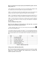
Name / Code
Description
Code / Value
View
Calibration
zero and span calibration value. The values displayed
in this function are valid only after Calibration ( F16 &
F17 ) has been successfully completed.
F19
Key-in Zero
Allows you to key-in zero calibration value in case of
memory loss in the field.
F20
Key-in Span
Allows you to key-in a known span calibration value in
case of memory loss in the field.
F21
Factory Reset
This sub-menu will reset all parameters in the “F” and
“A” menu to the default settings.
USE WITH
CAUTION!
Chapter 5: User Menu
5.1 User Menu Descriptions
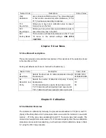
This section provides more detailed descriptions of the selections of the selections found
in the User Menu Chart.
Factory-set defaults are shown in bold with a checkmark (√).
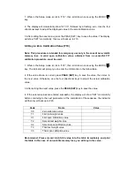
Name / Code
Description
Code / Value
A1
Baud Rate
Selects the baud rate for data transmission through
the serial port.
300,600,1200,
2400,4800,9600
A2
Data Bits and
Parity
Selects the number of data bits and parity of serial
transmission.
“8n”=8 data bits with no parity bit and one stop bit.
“7O”=7 data bits with odd parity bit and one stop bit.
“7E”=7 data bits with even parity bit and one stop bit.
8n√
7O
7E
Chapter 6: Calibration
6.1 Calibration Overview
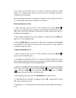
The indicator is calibrated by following the procedures embedded in F16 (Zero) and F17
(Span) of the Setup Menu. Each procedure enters a value into the indicator’s non-volatile
memory – F16 the zero value (deadweight) and F17 the span value (test weight). The
minimum test weight that can be used is 1% of full-scale capacity. After the two calibration
procedures are executed successfully, you should record both calibration values in Table
6-1 using the F18 View procedure.


