AI1401 Reader User Guide
3-4
The RS
–
232C connector can also be used during system operation, if real-time com-
munications are required. Using the RS
–
232C connector, the AI1401 Reader supports
the following real-time methods of operation:
•
AI1401 Reader to host using direct RS
–
232C cable connection
•
AI1401 Reader to host using RF modems from the remote location to the base
location
•
AI1401 Reader to on-site handheld computer via an RS
–
232C cable connection
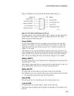
Figure 3-2 defines the pin positions of the RS
–
232C connector.
Figure 3-2 RS
–
232C DB9 Connector Pin-out
Auxiliary Input/Output Connector
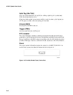
The user's input/output (I/O) interface must provide a DB9 plug connector to termi-
nate on the AI1401 Reader. The user must provide an actuator signal (trigger) that
turns on RF power for reading tags. After tag data is acquired, RF power should be
shut off to conserve power.
Note: When connecting the 10-1401-01 Reader or the 10-1401-04 Reader to a termi-
nal emulator, you may need to isolate Pin 9 of the I/O interface cable.
Summary of Contents for AI1401
Page 2: ......
Page 5: ...Contents...
Page 6: ......
Page 9: ...1 Before You Begin...
Page 10: ......
Page 13: ...2 Overview...
Page 14: ......
Page 20: ...AI1401 Reader User Guide 2 8...
Page 21: ...3 AI1401 Reader Interface Capabilities...
Page 22: ......
Page 27: ...A Firmware Command Groups and Parameters...
Page 28: ......
Page 39: ...B AI1401 Character Conversion...
Page 40: ......
Page 42: ...AI1401 Reader User Guide B 4...


