INSTALLATION
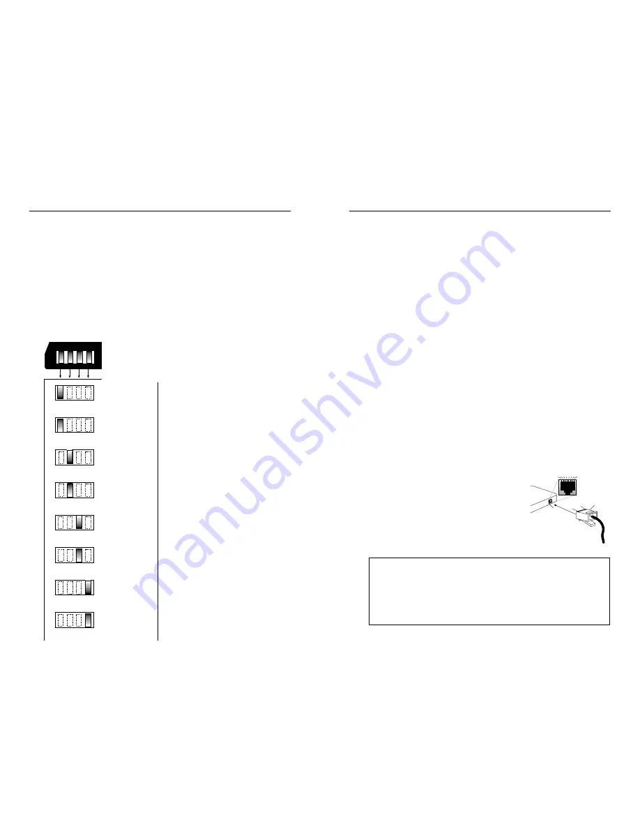
Setting DIP Switch
NOTE: Set DIP switch (located on Media Converter Slide-in-Module
circuit board) BEFORE installing Media Converter Slide-in-Module in
the Media Conversion Center.
DIP switch settings shown below are set to configure the bridging media
converter for the site installation.
To set network speed(s) and operating mode(s), use a very small
flatblade screwdriver or similar
device and refer to the table at the
left and to the examples on the
next page to set DIP switch for the
site installation.
NOTE: Auto-negotiation is
designed so that a twisted-pair link
will not become operational until
matching capabilities exist in the
devices installed at both ends of
the 802.3u twisted-pair network.
• When auto-negotiation is
enabled using switch #1, the
bridging media converter
“advertises” rate and mode
capabilities to the network.
Switch #2 and switch #3 are
used selectively to set the
twisted-pair rate and mode to
be “advertised” OR to allow the
full range of rates and modes.
• When auto-negotiation is
disabled using switch #1, the
bridging media converter does
not “advertise” rate and mode
capabilities to the network
Switch #2 and switch #3 are
used to set twisted-pair rate and
mode.
CABLE SPECIFICATIONS
Copper Cable Specifications
10BASE-T
The physical characteristics of 10BASE-T cable must meet or exceed
IEEE 802.3 10BASE-T specifications. Though Category 3 cable is
adequate for the 10BASE-T installation, Category 5 cable is strongly
recommended, since Category 3 cable can not be used for a later
upgrade to 100BASE-TX. DO NOT USE FLAT OR SILVER SATIN WIRE.
100BASE-TX
The physical characteristics of 100BASE-TX cable must meet or exceed
IEEE 802.3 100BASE-TX specifications. Category 5 cable or better is
required. Either shielded twisted pair (STP) or unshielded twisted pair
(UTP) can be used. DO NOT USE FLAT OR SILVER SATIN WIRE.
Category 3:
Gauge
24 to 22 AWG
Attenuation 6.5
dB/100’ @ 10 MHz
Differential Characteristic Impedance
100
Ω
±15%
Category 5:
Gauge
24 to 22 AWG
Attenuation 22
dB/100’ @ 100 MHz
Differential Characteristic Impedance
100
Ω
±15%
Maximum Cable Distance:
100 meters (330 feet)
RJ-45
P
LUG
RJ-45
J
ACK
1
8
2 3 4 5 6 7
1
8
The two active pairs in a 10BASE-T or 100BASE-TX
network are pins 1 & 2 and pins 3 & 6. Use only
dedicated wire pairs (such as blue/white &
white/blue, orange/white & white/orange) for the
active pairs.
The two wires in each pair of the cable must be
twisted together for the entire length of the
segment and kept twisted to within approximately
1/2 inch of any connector to ensure the integrity of
the signal-carrying characteristics of the
unshielded wire pair.
NOTE: Media converter is pinned as DTE device.
Twisted-pair Copper Straight-Through /Crossover Configurations
Crossover Cable
at RJ-45 Plug
Bridging Media Converter Network Device
RJ-45 Male . . . . . . . . . . . . .RJ-45 Male
1
(TX+)
. . . . . . . . . . . . . . . 3
2
(TX-)
. . . . . . . . . . . . . . . 6
3
(RX+)
. . . . . . . . . . . . . . 1
6
(RX-)
. . . . . . . . . . . . . . . 2
Straight-Through Cable
at RJ-45 Plug
Bridging Media Converter Network Device
RJ-45 Male . . . . . . . . . . . . .RJ-45 Male
1
(TX+)
. . . . . . . . . . . . . . . 1
2
(TX-)
. . . . . . . . . . . . . . . 2
3
(RX+)
. . . . . . . . . . . . . . 3
6
(RX-)
. . . . . . . . . . . . . . . 6
Twisted-pair Auto-negotiation ON
Twisted-pair Auto-negotiation OFF
Twisted-pair FULL-DUPLEX
Twisted-pair HALF-DUPLEX
Twisted-pair 100BASE-TX
Twisted-pair 10BASE-T
Fiber FULL-DUPLEX
Fiber HALF-DUPLEX
UP
DOWN
UP
DOWN
UP
DOWN
UP
DOWN
Config
Switches
1 2 3 4
Summary of Contents for C/E-PSW-FX-03
Page 9: ......


