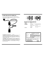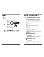
CABLE SPECIFICATIONS
The physical characteristics of the media cable must meet or exceed IEEE 802.3 specifications.
Fiber Cable
Multimode Cable Recommended:
62.5 / 125 µm multimode fiber
Optional:
100 / 140 µm multimode fiber
85 / 125 µm multimode fiber
50 / 125 µm multimode fiber
Singlemode Cable Recommended:
9/125 µm singlemode fiber
Bit
error rate:
≤
10
-9
C/E-TBT-FRL-04
850nm multimode
Fiber-optic Transmitter Power:
min: -16.0 dBm
max: -10.0 dBm
Fiber-optic Receiver Sensitivity:
min: -29.5 dBm
max: -7.2 dBm
Maximum Cable Distance:
2 kilometers (6,600 feet)
C/E-TBT-FRL-04 (L)
1300nm multimode
Fiber-optic Transmitter Power:
min: -19.0 dBm
max: -15.0 dBm
Fiber-optic Receiver Sensitivity:
min: -34.0 dBm
max: -14.0 dBm
Maximum Cable Distance:
5 kilometers (16,500 feet)
C/E-TBT-FRL-04 (MT)
850nm multimode
Fiber-optic Transmitter Power:
min: -16.0 dBm
max: -10.0 dBm
Fiber-optic Receiver Sensitivity:
min: -29.5 dBm
max: -7.2 dBm
Maximum Cable Distance:
2 kilometers (6,600 feet)
C/E-TBT-FRL-04 (SC)
850nm multimode
Fiber-optic Transmitter Power:
min: -16.0 dBm
max: -10.0 dBm
Fiber-optic Receiver Sensitivity:
min: -29.5 dBm
max: -7.2 dBm
Maximum Cable Distance:
2 kilometers (6,600 feet)
C/E-TBT-FRL-04 (SM)
1300nm singlemode - with ST connectors
Fiber-optic Transmitter Power:
min: -23.0 dBm
max: -14.0 dBm
Fiber-optic Receiver Sensitivity:
min: -34.0 dBm
max: -14.0 dBm
Typical Cable Distance*:
20 kilometers (66,000 feet)
C/E-TBT-FRL-04 (LH)
1300nm singlemode - with ST connectors
Fiber-optic Transmitter Power:
min: -17.0 dBm
max: -12.0 dBm
Fiber-optic Receiver Sensitivity:
min: -34.0 dBm
max: -14.0 dBm
Typical Cable Distance*:
20 kilometers (66,000 feet)
C/E-TBT-FRL-04 (XC)
1300nm singlemode - with SC connectors
Fiber-optic Transmitter Power:
min: -23.0 dBm
max: -14.0 dBm
Fiber-optic Receiver Sensitivity:
min: -34.0 dBm
max: -14.0 dBm
Typical Cable Distance*:
20 kilometers (66,000 feet)
*Actual distance dependent upon physical characteristics of network installation.
Copper Cable and Connector
Twisted pair connection requires two active pairs configured as straight through.
The two active pairs in an Ethernet™ network are pins 1 & 2 and pins 3 & 6. Use
only dedicated wire pairs (such as blue/white & white/blue, orange/white &
white/orange) for the active pairs.
Category 3 or better twisted-pair copper wire is required. Either shielded twisted-
pair (STP) or unshielded twisted-pair (UTP) can be used. DO NOT USE FLAT OR
SILVER SATIN WIRE.
INSTALLATION
Install Slide-In-Module in E-MCC-1600 Chassis
NOTE: Media Converter Slide-in-Modules can be installed in any installation
slot, in any order.
•
Remove Media Converter Slide-in-Module protective plate from selected
installation slot by removing two (2) screws that secure plate to front of
E-MCC-1600 chassis.
•
Carefully slide Media Converter Slide-in-Module into installation slot,
aligning Media Converter Slide-in-Module with installation guides.
NOTE: Ensure that the Media Converter Slide-in-Module is firmly seated
against the backplane.
•
Secure Slide-in-Module by securing panel fastener screw attached to
Slide-in-Module to E-MCC-1600 chassis.
Install Cable
NOTE: See pages 6 and 7 for cable specifications and configurations.
COPPER
EITHER STRAIGHT-THROUGH OR CROSSOVER CABLE CAN BE USED
BETWEEN THE MEDIA CONVERTER AND A HUB, TERMINAL DEVICE,
TRANSCEIVER, SWITCH, OR NETWORK INTERFACE CARD (NIC).
•
Locate or build 10BASE-T-compliant cables with either straight-
through or crossover configuration and with male RJ-45 plug
connectors at both ends.
•
Connect male RJ-45 plug connector at one end of cable to media
converter RJ-45 jack connector.
•
Connect male RJ-45 plug connector at other end of cable to
10BASE-T hub, terminal device, transceiver, switch, or network
interface card (NIC) RJ-45 jack connector.
FIBER
•
Locate or build 10BASE-FL-compliant fiber cable with male two-
stranded TX to RX connectors at both ends.
•
Connect male TX and RX cable connectors at one end of cable to
TX and RX female connectors, respectively, on media converter.
•
Connect male TX and RX cable connectors at other end of cable
to RX and TX connectors of 802.3 compliant fiber device


