Port One - Duplex Fiber Optic
1000Base-SX
Port Two - Single Mode Fiber-Optic
Single Fiber, 1000Base-LX
2
CFMFF13xx-28x
24-hour Technical Support: 1-800-260-1312 -- International: 00-1-952-941-7600
Part Number
CFMFF1329-280
SC, 850 nm multimode
220 m
(721 ft)**
SC, 1310 nm (TX)/1550 nm (RX)
20 km
(12.4 miles)
CFMFF1329-281
SC, 850 nm multimode
220 m
(721 ft)**
SC, 1550 nm (TX)/1310 nm (RX)
20 km
(12.4 miles)
CFMFF1329-280 and CFMFF1329-281 are intended to be
installed in the same network where one is the local converter
and the other is the remote converter.
CFMFF1329-282
SC, 850 nm multimode
220 m
(721 ft)**
SC, 1310 nm (TX)/1550 nm (RX)
40 km
(24.8 miles)
CFMFF1329-283
SC, 850 nm multimode
220 m
(721 ft)**
SC, 1550 nm (TX)/1310 nm (RX)
40 km
(24.8 miles)
Unless otherwise indicated, the distances listed are the typical maximum cable
distance. The actual maximum cable distances are dependent upon the physical
characteristics of the network installation. TX = transmit, RX = receive.
** Minimum Cable Distance:
2 meters
Typical Maximum Cable Distance:
220 meters for 160/500MHz•Km
270 meters for 200/500MHz•Km
CFMFF1329-282 and CFMFF1329-283 are intended to be
installed in the same network where one is the local converter
and the other is the remote converter.
Installation
CAUTION: Wear a grounding device and observe electrostatic discharge
precautions when setting the jumper, the 4-position switch, and when installing
the slide-in-module. Failure to observe this caution could result in damage to,
and subsequent failure of, the media converter.
Set the Hardware/Software Jumper
•
The jumper is located on the circuit board.
•
Use small needle-nose pliers to set the recessed switches.
Hardware
The media converter mode is determined by the
4-position switch settings
(see page 4).
Software
The media converter mode is determined by the
most-recently saved, on-board microprocessor
settings.
(See SNMP on page 6.)
CFMFF1414-280
SC, 1310 nm single mode
10 km
(6.2 miles)
SC, 1310 nm single mode
10 km
(6.2 miles)
3
techsupport@transition.com -- Click the “Transition Now” link for a live Web chat.
Installation
-- Continued
Set the 4-position switch
•
The 4-position switch is located on the circuit board.
•
Use a small flat-blade screwdriver to set the recessed switches.
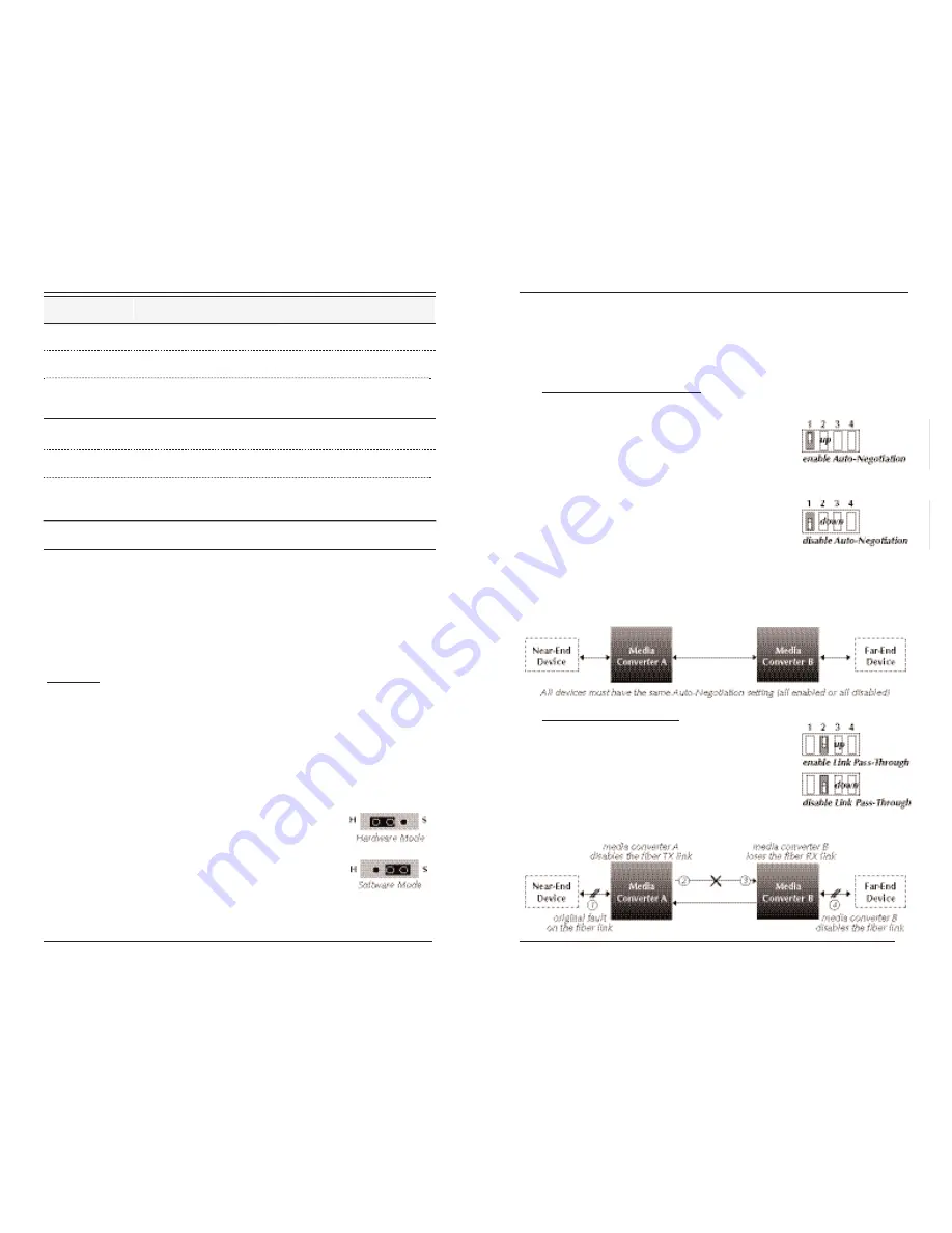
Fiber Auto-Negotiation
(Switch 1)
up
= Enable fiber Auto-Negotiation for both the single mode and the
multimode ports.
When fiber Auto-Negotiation is enabled:
The pause feature can be set using switches
3 and 4. (See page 4).
down = Disable fiber Auto-Negotiation for both the single mode and the
multimode ports.
When fiber Auto-Negotiation is disabled:
Switches 3 and 4 will not function. The
media converter adopts the pause setting
from the end device at the other end of the
fiber cable.
NOTE:
All devices in the network, including the end devices, must have
Auto-Negotiation enabled, or all devices must have Auto-Negotiation
disabled. Otherwise, the devices in the network will not link up.
Link Pass-Through
(Switch 2)
up
= Enable Link Pass-Through.
down = Disable Link Pass-Through.
The Link Pass-Through feature allows the media
converter to monitor both fiber RX (receive) ports for
loss of signal. In the event of a loss of an RX signal
on one media port, the media converter will
automatically disable the TX (transmit) signal of the
other media port, thus, “passing through” the link loss.


