background image

CPSMP-200

8

Tech Support:  

1-800-260-1312

-- International:  

00-1-952-941-7600

-- (24 hours)

Replace the Fuse

CAUTION:  Ensure that the power supply module has been disconnected
from the external power source and the module’s On/Off switch has been
set to “0”.  Failure to observe this caution could result in damage to, and
subsequent failure of, the power supply module.

NOTE:  

The CPSMP-200 power supply module may be “hot swapped” (i.e.,

serviced while the chassis is in operation) 

provided the module to be serviced

has been disconnected from its external power supply and the module’s
On/Off switch has been set to “0”.

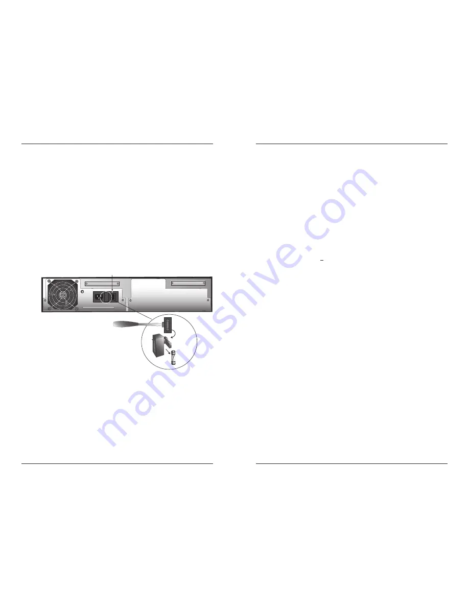
To replace the fuse in the CPSMP-200 power supply module:

1.

Ensure the On/Off switch on the power supply module is set to 

“0”

.

2.

Disconnect the AC power cord from the external power source.

3.   From the inside edge of the power receptacle, insert a small flat blade

screwdriver into the groove on the front, inside edge of the fuse holder
and carefully pry the fuse holder from the power supply module.

4.

Carefully remove the fuse from the fuse holder.

5.

Install a 

same size and rating

replacement fuse in the fuse holder.

6.

Return the fuse holder and fuse to the installation position in the power
supply module.  Snap the fuse holder into place.

7.

See the “

Connect to External Power

” section (page 5) for instructions on

re-connecting the power supply module to the external power source.

I
0

On/Off Switch

Fuse Holder

Fuse

techsupport@transition.com

-- Click the 

“Transition Now”

link for a live Web chat.

9

Technical Specification

For use with Transition Networks Model CPSMP-200 or equivalent.

Standards

UL Listed EN60950; FCC & CISPR Class A&B; 
EN61000-3-2 Class D

CE Mark

Dimensions

8.3" x 8.4" x 2.7" (211 mm x 211 mm x 69 mm)

Weight

1 lb. (0.45 kg) approximately

Power Input

100-240 V, 47/63Hz, 0.62-1.5 Amp, 
(typical with a fully-loaded chassis)

Voltage Tolerance

± 10%

Low-Line Input Current

3.3A max.

Inrush Current

40A max.( peak starting current) @ high line

Transient Recovery Time

1ms  max.

Power Output

12VDC at 10.83 Amp max.

Power Factor  

>

0.95 (no inductive or capacitive distinction)

Fuse

4 Amp/250 V  

MTBF

60,000 hours (MIL217F2 V5.0) (MIL-HDBK-217F)
248,000 hours (Bellcore7 V5.0)

Environment

Tmra*:

0 to 60°C (32 to 140°F )

Storage Temperature:  

-20 to 85°C (-4 to 185°F)

Humidity:

5 to 95%, non condensing 

Altitude:

0 to 10,000 feet

Warranty

Lifetime

*Manufacturer’s rated ambient temperature:  Tmra range for this power supply
module depends on the physical characteristics and the installation configuration
of the Transition Networks 

PointSystem™

chassis in which this module will be

installed.  

Summary of Contents for CPSMP-200

Page 1: ...tch that when set to I allows the module to supply power to the PointSystem chassis A Primary Secondary switch that allows the module to be configured as the primary or as the secondary power supply A Management Manual switch that allows the PointSystem software to control and override the physical setting of the Primary Secondary switch A fan to cool the interior of the PointSystem chassis A hand...

Page 2: ...e power supply module has the configuration as set by the Primary Secondary switch The software interface cannot change the setting I 0 Manual Management Secondary Primary techsupport transition com Click the Transition Now link for a live Web chat 3 Primary Secondary Switch The Primary Secondary switch allows the module to be configured as the Primary or as the Secondary power supply As the Prima...

Page 3: ...ly module into the installation slot aligning the module with the installation guides Ensure that the power supply module is firmly seated against the chassis backplane 5 Carefully install the two 2 screws retained in step 1 through the power supply module and into the chassis Rotate the screws clockwise to secure I 0 I 0 I 0 Primary Secondary Switch and Management Manual Switch techsupport transi...

Page 4: ...2 screws that secure the power supply module to the chassis Retain the screws for installing the replacement module 4 Carefully slide the power supply module out of the chassis I 0 On Off Switch AC Power Cord I 0 I 0 techsupport transition com Click the Transition Now link for a live Web chat 7 5 Set the Primary Secondary switch and the Management Manual switch on the replacement power supply modu...

Page 5: ...ion in the power supply module Snap the fuse holder into place 7 See the Connect to External Power section page 5 for instructions on re connecting the power supply module to the external power source I 0 On Off Switch Fuse Holder Fuse techsupport transition com Click the Transition Now link for a live Web chat 9 Technical Specification For use with Transition Networks Model CPSMP 200 or equivalen...

Page 6: ...t is available 24 hours a day US and Canada 1 800 260 1312 International 00 1 952 941 7600 Transition Now Chat live via the Web with Transition Networks Technical Support Log onto www transition com and click the Transition Now link Web Based Seminars Transition Networks provides seminars via live web based training Log onto www transition com and click the Learning Center link E Mail Ask a questi...

Page 7: ... the equipment is operated in a commercial environment This equipment generates uses and can radiate radio frequency energy and if not installed and used in accordance with the instruction manual may cause harmful interference to radio communications Operation of this equipment in a residential area is likely to cause harmful interference in which case the user will be required to correct the inte...

Reviews: