CPSMP-210 48VDC and CPSMP-220 24VDC Power Supplies
6
24-Hour Technical Support: 1-800-260-1312 -- International: 00-1-952-941-7600
!
Installation—continued
Configuring two power supplies in one chassis
To set up power supply redundancy, set one power supply to master,
(which supplies
power to the entire chassis)
and the other to slave. In this mode, the slave power
supply is in stand-by mode and takes over in the event of a master power-supply
failure. See Figure 3.
I
MPORTANT
:
•
In a multiple power supply chassis, one power supply must be set to master. If
both modules are set to slave neither will supply sufficient power to the chassis.
•
Power supply load sharing
(configuring multiple supplies as masters in a chassis)
is not recommended
(no load balancing capability)
.
Installing the power supply in a PointSystem chassis
WARNING: Do not connect the power supply to an external power source before
installing it into the chassis. Failure to observe this warning could result in an
electrical shock, even death.
Note:
The power supply module can be hot swapped
(i.e., swapped while the chassis
is in operation)
provided the power supply’s ON/OFF switch is in the OFF
position, and it has been disconnected from its external power source.
To install the power supply in either the CPSMC18xx-xxx or the CPSMC19xx-100
PointSystem chassis:
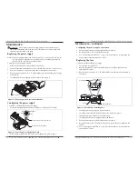
1. Slide the power supply ON/OFF switch to OFF, as shown in Figure 4.
Master
Slave
Management
Manual
Figure 3: Configuration Switch Positions
!
OFF
ON
Power Supply ON/OFF Switch
+
-
Power ON LED
Terminal Block
Figure 4: Power Supply Power ON LED, Terminal Block and ON/OFF Switch
techsupport@transition.com -- Click the “Transition Now” link for live Web chat.
7
Installation—continued
Installing the power supply into a PointSystem chassis—continued
2. Remove and keep the two (2) 6-32 philips head screws securing the power supply
slot cover on the rear of the chassis and remove it. See Figure 5.
3. Set the power supply configuration switch to the desired positions. See Figure 6.
4. Slide the power supply into the installation slot as shown in Figure 7, aligning it
with the installation guides—make sure that it is fully seated in the chassis slot.
5. Re-install and tighten the two (2) 6-23 philips head screws to secure the power
supply to the chassis.
Chassis
Power-Supply
Slot Cover
6-32 Philips
Chassis
Power Supply
Guide
6-32 Philips
Figure 5: Remove Chassis Power-Supply Slot Cover
Figure 7: Power Supply Installation
Figure 6: Configuration Switch
Master
Slave
Management
Manual
CPSMP-210 48VDC and CPSMP-220 24VDC Power Supplies


