AUI Connection: Connection of the transceiver to a device or host
requires the use of AUI cable(s). Use only an IEEE 802.3 equivalent AUI
cable. The cable shell should be grounded.
Connector Legend: Pin(s)
1 Logic Ref.
9 Collision-
(15-Pin Male D)
2 Co
10 Transmit-
3 T
11 Logic Ref.
4 Logic Ref.
12 Receive-
5
13 Power
6 Power Return
14 Logic Ref.
7 N/C
15 N/C
8 Logic Ref.
FCC Regulations:
NOTE: This equipment has been tested and found to comply with the
limits for a Class A digital device, pursuant to Part 15 of the FCC rules.
These limits are designed to provide reasonable protection against
harmful interference when the equipment is operated in a commercial
environment. This equipment generates, uses, and can radiate radio
frequency energy and, if not used in accordance with the instruction
manual, may cause harmful interference to radio communications.
Operation of this equipment in a residential area is likely to cause
harmful interference in which case the user will be required to correct
the interference at his own cost.
NOTE: This digital apparatus does not exceed the Class A limits for
radio noise for digital apparatus set out on the radio interference
regulations of the Canadian Department of Communications.
Trademarks:
TRANSITION Networks is the trademark of TRANSITION Networks, Inc.
Ethernet is a registered trademark of Xerox Corporation, Inc.
AMP is a registered trademark of AMP, Inc.
Technical Support:
For more information about this product or other TRANSITION
Networks products, call you local Transition distributor. Or contact us
by phone at (612) 941-7600 or fax at (612) 941-2322.
Ethernet Dual Coaxial Transceiver
Models E-CX-MC22, MC23, MC24, & MC25
User's Guide
Manual #7323.B REV 4/94
About the Ethernet Dual Coaxial Transceiver:
The TRANSITION Networks 10Base2 / 10Base5 Dual Transceiver is
designed to provide dual AUI connections to the coaxial (Thick and
Thin) Ethernet environment. The different taps are: P/N 6900 with the
non-intrusive (vampire) tap; P/N 6901 with the N-Series intrusive tap;
P/N 6902 with the BNC-T connector; and P/N 6903 with the BNC
vertical adapter.
Features of the Ethernet Dual Coaxial Transceiver:
-Provides two isolated AUI connections to the network
-An internal SQE enable or disable jumper
-Compliant with Ethernet IEEE 802.3
-Choice of coax connections for 50 ohm thick or thin coax
-Two year warranty
-No external power required. Power is provided by the dual
AUI connections.
Using the Ethernet Dual Coaxial Transceiver:
P/N 6900: The transceiver is attached to the thick coax via the AMP
coax tap assembly, part number 228752-1. NOTE: To install onto the
thick coax, an AMP installation tool kit, part number 228917-1 is
required. For complete installation instructions, read the instructions
provided with the AMP coax tap kit. Failure to install the coax tap
properly may cause damage to the transceiver and network.
P/N 6901: The transceiver is connected to the thick coax through the
female N connectors that are attached. To complete the assembly
provided, remove the 2 screws on the transceiver, install AMP (P/N
221914-1) connector into the transceiver, re-install screws.
P/N 6902: The transceiver is connected to the thin coax through the
attached BNC T connector. To complete the assembly provided,
remove the 2 screws on the transceiver install AMP (P/N 221918-1)
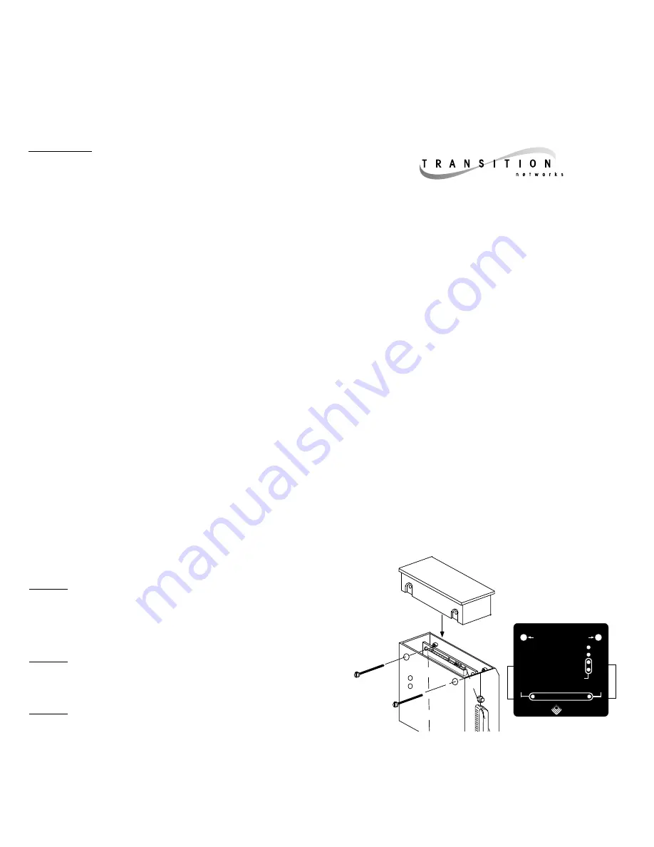
TRANSCEIVER
ASSEMBLY
AMP Tap
ASSEMBLY
To Install
1. Remove screws from Transceiver.
2. Slide AMP tap into Transceiver.
3. Re-install screws into Transceiver.
4. Connect completed unit to the network.
E-CX-MC2X
Active
Collision
Port 2
Port 1
Jabber
Port 1
Port 2
Power
Remove screws to release tap
E N G I N E E R I N G , I N C .
Ethernet™
Dual Coaxial
Tap Transceiver
TRANSITION
Front View / LED locations


