E-PSW-SX-01
INSTALLATION
NOTE: Ensure that the installation location is well-ventilated and near a
standard AC electrical outlet.
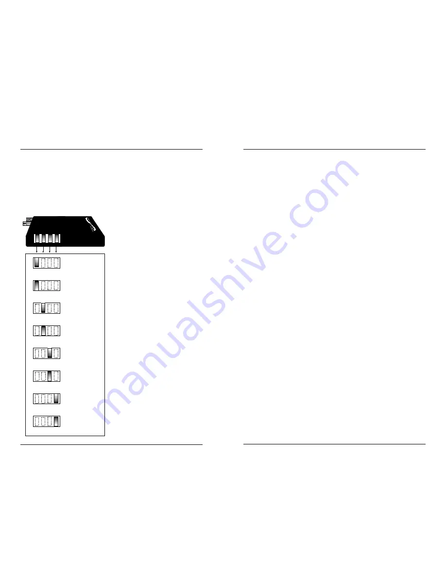
Setting DIP Switch
DIP switch settings shown below are set to configure the bridging media
converter for the site installation:
To set network speed(s) and
operating mode(s), use a VERY small
flatblade screwdriver or similar
device and refer to the table at the
left and to the examples on the next
page to set DIP switch for the site
installation.
NOTE: Auto-negotiation is designed
so that a twisted-pair link will not
become operational until matching
capabilities exist in the devices
installed at both ends of the 802.3u
twisted-pair network.
•
When auto-negotiation is
enabled using switch #1, the
bridging media converter
“advertises” rate and mode
capabilities to the network.
Switch #2 and switch #3 are
used selectively to set the
twisted-pair rate and mode to be
“advertised” OR to allow the full
range of rates and modes.
•
When auto-negotiation is
disabled using switch #1, the
bridging media converter does
not “advertise” rate and mode
capabilities to the network
Switch #2 and switch #3 are
used to set twisted-pair rate and
mode.
Connecting Fiber Cable to TX/RX Connector
(100BASE-SX)
100BASE-SX AND THE FAST ETHERNET COLLISION DOMAIN
•
Refer to the 512-Bit Rule (page 7) before installing half-duplex
100BASE-SX cable.
•
Using full-duplex fiber cable avoids collision domain
considerations and extends distances up to 300 meters.
•
NOTE: A Fast Ethernet collision domain can have ONLY ONE
CLASS I repeater OR TWO CLASS II repeaters.
INSTALLING CABLE
To install 100BASE-SX cable:
1. Locate or build 100BASE-SX cables:
•
100BASE-SX compliant (page 11)
•
with male transmit (TX) and receive (RX) fiber connectors
installed at both cable ends.
2. Connect transmit cable connector at one end of fiber cable to
bridging media converter connector marked with an “outbound”
arrow; connect receive cable connector to bridging media
converter connector marked with an “inbound” arrow.
3. Connect other end of cable installed at transmit (TX) connector of
bridging media converter to receive (RX) connector on network
device; connect other end of cable installed at receive (RX)
connector of bridging media converter to transmit (TX) connector
on network device.
Powering the Bridging Media Converter
To power ON the bridging media converter:
1. Locate power receptacle on back of bridging media converter
2. Connect the bridging media converter power connector end of the
power supply adapter to the power receptacle on the back of the
Transition Network’s bridging media converter.
3. Connect the external power connector end of the power supply
adapter to external AC power.
NOTE: After the power supply adapter is connected to the bridging media
converter and to external power, the green Power LED is illuminated.
9
4
Twisted-pair Auto-negotiation ON
Twisted-pair Auto-negotiation OFF
Twisted-pair FULL-DUPLEX
Twisted-pair HALF-DUPLEX
Twisted-pair 100BASE-TX
Twisted-pair 10BASE-T
Fiber FULL-DUPLEX
Fiber HALF-DUPLEX
UP
DOWN
UP
DOWN
UP
DOWN
UP
DOWN
Config
Switches
1 2 3 4


