background image


EO2P User Guide  |Page  9 


33706 Rev. A 


Installation  


Install Cautions and Warnings 

 Elevated Operating Ambient

: If installed in a closed cabinet, the operating ambient 

temperature of the rack environment may be greater than room ambient. Therefore, 
consideration should be given to installing the equipment in an environment compatible with 
the maximum ambient temperature (Tma) specified by the manufacturer. 

Reduced Air Flow

: Installation of the equipment should be such that the amount of air flow 

required for safe operation of the equipment is not compromised. 

Mechanical Loading

: Mounting of the equipment should be such that a hazardous condition 

is not achieved due to uneven mechanical loading. Do not place any equipment on top of a 
rack-mounted unit.


Circuit Overloading

: Consideration should be given to the connection of the equipment to 

the supply circuit and the effect that overloading of the circuits might have on overcurrent 
protection and supply wiring. Appropriate consideration of equipment nameplate ratings 
should be used when addressing this concern. 


Inter-building and Protection Requirements

: These products incorporate surge 

protection.  
 

Not Designed for Use in Life Support Equipment or Applications

: These products are 

not designed for use in life support equipment or applications that would cause a life-
threatening situation if any such product failed. Do not use this product in these types of 
equipment or applications.  
 

Export Rules

: With respect to the product described herein, the user or recipient, in the 

absence of appropriate U.S. government authorization, agrees: 
1) Not to re-export the or release any such information consisting of technology, 
software or source code controlled for national security reasons by the U.S. Export 
Control Regulations (“EAR”), to a national of EAR Country Groups D:1 or E:2;  
2) Not to export the direct product of such technology or such software to EAR Country 
Groups D:1 or E:2, if such technology or software and direct products thereof are 
controlled for national security reasons by the EAR; and 
3) In the case of technology controlled for national security reasons under the EAR 
where the direct product of the technology is a complete plant or component of a plant, 
not to export to EAR Country Groups D:1 or E:2 the direct product of the plant or major 
component thereof, if such direct product is controlled for national security reasons by 
the EAR, or is subject to controls under the U.S. Munitions List (“USML”). 
At all times hereunder, the recipient of such information agrees that they shall be 
deemed to have manually signed this document in connection with their receipt of any 
such information.  


Summary of Contents for E02PD4052-111

Page 1: ...33706 Rev A EO2Pxx4052 111 Ethernet over 2 Wire Extender With PoE User Guide...

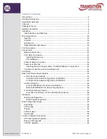
Page 2: ...10 100 1000Base T Copper Port 14 Two Wire Connection Local to Remote Unit 14 Grounding 14 Back Panel Device Power Options 15 2 Wire Connection Options 15 2 Position Terminal Block Plug Option TN 28992...

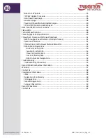
Page 3: ...Data Throughput over Distance 1518 byte frames 51 Power over Distance 51 Ethernet Over 2 Wire Power Distance Calculator 52 RJ45 Cable Configurations 53 One Pair 2 Wire RJ45 53 Two Pair 4 Wire RJ45 53...

Page 4: ...devices at distances beyond the typical 100m Ethernet cable limitation The EO2P leverage the existing 18 24 AWG unshielded twisted pair CAT6 5 CAT3 or 2 wires of other 18 24 AWG UTP cable cabling infr...

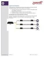
Page 5: ...and power to IP devices such as wireless access points WAPs or VoIP phones Bridging between two networks using a 2 wire infrastructure Conversion of analog surveillance systems to IP based cameras and...

Page 6: ...per 1000 ft Cable with less DC resistance may increase distance Web browser configurable Web based management of both local and remote Plug and Play installation Field upgradeable firmware Can be mana...

Page 7: ...EO2P User Guide Page 7 33706 Rev A Device Views EO2PSE4052 111 Local PSE Unit EO2PD4052 111 Remote PD Unit...

Page 8: ...2 Position Terminal Block Plug Option TN 28992 One 25148 90W Power Adapter o includes country specific power cord Save the packaging for possible future use Related Information A printed Quick Start...

Page 9: ...ucts are not designed for use in life support equipment or applications that would cause a life threatening situation if any such product failed Do not use this product in these types of equipment or...

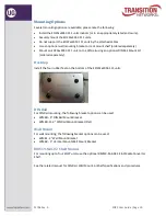
Page 10: ...l using an optional DIN Rail Mount Kit ordered separately Desktop Install the four rubber feet on the bottom of the EO2Pxx4052 111 units DIN Rail For DIN Rail mounting the following bracket options ca...

Page 11: ...nd provides a PoE 10 100 1000Base T RJ 45 connection or a 100 1000Base X SFP connection Connections This section illustrates and describes connecting the EO2PSE4052 111 Local PSE unit with GB combo RJ...

Page 12: ...with the Multi Sourcing Agreement MSA ensuring interoperability with all other MSA compliant networking devices See SFF 8472 Specification for details See the SFP manual for important Safety cautions...

Page 13: ...ctor Pluggables webpage For information on specific SFP characteristics unpacking installation connecting and removing see the specific SFP User Guide Connecting Single strand Fiber Cable Single fiber...

Page 14: ...the RJ 45 connector at one end of the cable to the EO2Pxx4052 111 10 100 1000Base RJ 45 port 3 Connect the RJ 45 connector at the other end of the cable to the 10 100 1000Base RJ 45 port on the other...

Page 15: ...d use a small slotted screwdriver to tighten the wires 2 Position Terminal Block Plug Option TN 28993 The provided 2 Position STR Terminal Block is a Female Socket 0 138 3 50mm 180 Free Hanging In Lin...

Page 16: ...ote EO2PD4052 111 Power Input Options The power input option for the EO2PD4052 111 Remote PD unit devices are 1 4 Pin mini DIN with the designated AC to DC adapter OR 2 2 Pin Terminal Block connectors...

Page 17: ...put option is shown and described below Note grip the power supply cable from the 48VDC IN 4 Pin Mini DIN connection with the flat topped grip facing up you will notice a slight slide before disconnec...

Page 18: ...ed PoE the remote unit does not provide PoE If you do not want PoE power from the Remote unit to the connected remote end device enable Auto Power Reset select PoE Power Down mode and ping an unused I...

Page 19: ...as described below Login page The Login page requires password access to the web pages Authentication Password This unit is password protected The default password is admin Please enter the correct p...

Page 20: ...never times out If a browser is closed with an active web session a log in from a different host results in a Other active session error message see below Message Other active session error There is a...

Page 21: ...lets you configure Auto Power Reset parameters and view current status Advanced lets you configure Hardware Reset and Factory Reset Status Menu Power displays current Power Information and Power over...

Page 22: ...ocal Unit MAC Address the EO2P Local unit s MAC address e g 00 c0 f2 58 3c 9d Peer Unit MAC Address the EO2P Remote Peer unit s MAC address e g 00 c0 f2 58 3c 9d Phy Tx Mbps the EO2P unit s Transmit s...

Page 23: ...e effect after system boot DHCP enabled at the dropdown select YES enabled or NO The default is YES enabled IPv4 address netmask displays the configured IPv4 address and Netmask e g 192 168 61 36 255...

Page 24: ...0000 0000 02c0 f2ff fe58 3c5a 128 IPv6 SLAAC address entry field for an IPv6 SLAAC address With SLAAC State Less Address Auto Configuration IPv6 hosts can configure themselves automatically when conne...

Page 25: ...nit can remain the default 192 168 0 2 and typically not impact network addressing while the IP address in the Local unit can be user defined The following operations and settings cannot be performed...

Page 26: ...parameters and configure Link Settings SFP Detection Settings Primary Link Mode Powersaving parameters Combo Port Speed e g 100 or 1000 Mbps speed currently configured Duplex e g FULL_DUPLEX or HALF_...

Page 27: ...efault is YES Only applies if Autonegotiation Enable above is set to YES Autonegotiation Advertise 10Mbit Half Duplex at the dropdown select NO or YES The default is YES Only applies if Autonegotiatio...

Page 28: ...Click the Log Out button to exit EO2P Web Configuration Ethernet page Messages Message Error Error detected when calling param value check function in set POWERSAVING GENERAL IDLE_TIME 3 Meaning At th...

Page 29: ...software information security password and FTP and HTTP software updates Hardware information Device Name the device model e g EO2PD4052 111 or EO2PSE4052 111 Device Description e g Ethernet and Power...

Page 30: ...ays 0h 3m 45s days hours minutes seconds Security New Configuration Password enter the updated security password and click Ok SW Update Status e g Ready initial status or Running downloading image or...

Page 31: ...ges and revert to the default parameter settings Log Out Click the Log Out button to exit EO2PD4052 111 Web Configuration Device page Messages Message Performing Hardware Reset Please wait until your...

Page 32: ...ttempt The EO2P device will reboot you will have to login again and usually the network mounted file will work the second time around as the file should be in the PC s cache You would typically have t...

Page 33: ...Reset button The message Performing Hardware Reset Please wait until your modem finishes initializing displays When finished you are logged out 6 At the login page enter your password and click the O...

Page 34: ...ng the upgrade process e g Upgrading PIC Copy complete and then PIC will automatically reboot Flash Upgrade status This page is updated automatically every 10 seconds The modem must be reset once the...

Page 35: ...steps 1 5 on both 192 168 0 1 and 192 168 0 2 web interfaces and then do steps 6 9 in order Note that you can start either upgrade first they can run at the same time and after your first time throug...

Page 36: ...is changed from Disabled to Power Down PoE Auto Mode or Timeout Mode The other APR Mode parameters are Power Down PoE Pings start after the configurable Device Reboot Time When the configurable number...

Page 37: ...ount of time before APR mode times out The default is 600 seconds 10 minutes This parameter is not configurable in Power Down PoE mode or in Timeout Mode Auto Power Reset Status Click the Auto Power R...

Page 38: ...Click the Advanced page link to update the status and then log in again Factory Reset Password you must enter the Password betera and then click the Ok button for a Factory Reset to default parameter...

Page 39: ...directed or click return to main page Message Performing Factory Reset Please wait until your modem finishes the initialization Meaning A factory reset from the Configuration Advanced menu path is in...

Page 40: ...EO2P 2 Wire output power in Watts 2 Wire Voltage Drop displays the voltage drop between the local and remote EO2Ps e g 0 140 Volts 2 Wire Power Drop displays the power drop between the local and remot...

Page 41: ...ch e g Classification Codes Match or Classification Codes Mismatch 2 Wire Power e g OFF or ON UART Status e g OK or Error Local 2 Wire Voltage Status e g Local 2 wire Power OFF or OK Local 2 Wire Curr...

Page 42: ...016 in the format ddmmyy day month year Transceiver e g 1000BASE SX DMI Information Temperature the SFP temperature in degrees Celsius Voltage the SFP voltage measurement in Volts TX Bias the SFP tran...

Page 43: ...emote Unit will automatically reset once the upgrade is completed The Remote Version will update once the Remote Unit has rebooted and completely initialized Status the current upgrade status e g blan...

Page 44: ...to factory default settings Blink rate is long on and then long off 40 second if you press and hold the back panel RESET button for over 40 seconds nothing happens when you release the RESET button No...

Page 45: ...n the SECURITY LED is lit solid on both devices this takes 2 3 minutes re boot both devices You can do this by unplugging and re plugging the power cord at the Local device if the Remote device is pow...

Page 46: ...O2PSE4052 110 Remote PD unit Power from 2 wire status Sourcing power from 2 wire Green ON Sourcing power from external PS Green BLINK If the external power supply 4 pin DIN or 2 Pin Terminal block is...

Page 47: ...100Mbps Green and Yellow ON link BLINK activity 10Mbps Yellow ON link BLINK activity POE Power Over Ethernet status Remote PD unit only No PD detected OFF Power applied Green ON Detect fault Yellow ON...

Page 48: ...ton on the back panel for a fixed amount of time see Back Panel RESET Button Functions on page 44 Power Source 4 Pin mini DIN or 2 Pin Terminal Block 48VDC 48V wall adapter 4 pin mini DIN TN 25148 Pow...

Page 49: ...the presence of power to the EO2Pxx4052 111 Universal AC input Full range 3 pole AC inlet IEC320 C14 Built in active PFC function No load power consumption 0 15W Energy Efficiency Level VI Comply with...

Page 50: ...pliance to EN55022 class B EN61000 3 2 3 FCC PART 15 CISPR22 class B CNS13438 class B GB9254 GB17625 1 EMC Immunity Compliance to EN61000 4 2 3 4 5 6 8 11 light industry level criteria A MTBF 348 7K h...

Page 51: ...a transfer rates and PoE available for the EO2P extenders as a function of wire length The RFC2544 test was run with 1518 byte frames The configuration options tested were Cat3 cable with only 2 wires...

Page 52: ...ps www transition com support library calculators This calculator should only be used for Transition Networks Ethernet Over 2 Wire Extender With PoE to provide approximate maximum distance and power c...

Page 53: ...h connector RJ45 Pin Number Designations RJ45 cables have eight color coded wires and the plugs have eight pins and conductors Eight wires are used as 4 pairs each representing positive and negative p...

Page 54: ...Designation 1 Green Stripe RX 2 Green RX 3 Orange Stripe Tx 4 Blue Not Used 5 Blue Stripe Not Used 6 Orange Tx 7 Brown Stripe Not Used 8 Brown Not Used T 568B Pins Pin Color Designation 1 Orange Stri...

Page 55: ...port disconnect and reconnect the twisted pair copper cable to restart the initialization process Restart the Ethernet switch Use the RESET button to reset the security configuration to defaults See p...

Page 56: ..._________________________________________________________________________ 6 Describe actions already taken to resolve the problem e g change mode reset etc ________ ___________________________________...

Page 57: ...rranty coverage contact Transition Networks Customer Support for a return authorization number Send the defective product postage and insurance prepaid to the following address Transition Networks Inc...

Page 58: ...ARRANTY IS YOUR ONLY REMEDY NO OTHER WARRANTIES SUCH AS FITNESS FOR A PARTICULAR PURPOSE ARE EXPRESSED OR IMPLIED TRANSITION NETWORKS IS NOT LIABLE FOR ANY SPECIAL INDIRECT INCIDENTAL OR CONSEQUENTIAL...

Page 59: ...is a Class A product In a domestic environment this product may cause radio interference in which case the user may be required to take adequate measures Achtung Dieses ist ein Ger t der Funkst rgren...

Page 60: ...mote PoC FW Version 22 Trademarks Notice All trademarks and registered trademarks are the property of their respective owners Copyright Restrictions 2017 Transition Networks All rights reserved No par...

Page 61: ...33706 Rev A Contact Us 10900 Red Circle Drive Minnetonka MN 55343 USA telephone 1 952 941 7600 toll Free 800 526 9267 fax 952 941 2322 sales transition com info transition com techsupport transition...

Reviews: